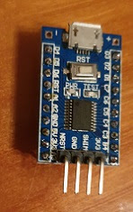
First i heated up my soldering iron to added some Dupont pins to 2 of this boards. At the bottom of this blogpost you see more pictures of the soldered pins
For programming a SWIM interface / ST Link is needed. Luckily some weeks earlier a simple ST Link arrived. This was a simple PCB with an USB port and the following connections
For programming a SWIM interface / ST Link is needed. Luckily some weeks earlier a simple ST Link arrived. This was a simple PCB with an USB port and the following connections
To protect the PCB i heat-shrinked this ST Link connector.
| Bottom [SWD] | Top [SWIM] |
| 3V3 | RST |
| SWD0 | GND |
| SWCLK | SWIM |
| GND | 5V |
With Dupont wires I made the following hardware connections between the programmer and the STM8S103F3P6 Breakout Board
| STM8S103F3P6 | Programmer |
| 3V3 | 3V3 |
| SWIM | SWIM |
| GND | GND |
| NRST | RST |
After configuring the Arduino IDE so that it can handle STM8 i successfully tested the board with the Blink program from the Arduino IDE (1.8.10) with the settings below.
For the other STM8S103F3P6 breakout board i used the long Dupont pins with male and female connectors. For the SWIM interface used male Dupont pins. I also added connectors to the + and - . The idea is that it can be easy placed in a project and the female headers still give easy access to all pins.
It is possible to use both variants on a breadboard.
| Tools Board: STM8S103F3 Breakout Board Programmer: ST-Link/V2 File Examples Examples for STM8S103F3 Breakout Board Generic_Examples 01 Basics Blink Some links: |
STM8S103F3P6 Breakout Board with Dupont pins
On one breakout board i used male ( and male pins with an angle) Dupont pins as often seen with this modules.For the other STM8S103F3P6 breakout board i used the long Dupont pins with male and female connectors. For the SWIM interface used male Dupont pins. I also added connectors to the + and - . The idea is that it can be easy placed in a project and the female headers still give easy access to all pins.
It is possible to use both variants on a breadboard.


No comments:
Post a Comment