To get to know my VNA i used my RF Demo kit that i already received some weeks ago.
The RF Demo kit board has 18 circuits, including circuits that can be used for calibration ( Short, Open Load and Thru).
I configured some parameters in my LiteVNA ( 0.1 MHz - 450 MHz , for more details see screenshot my previous post about my VNA. ) It are not the optimal settings to test a specific circuit, however this are settings to measure all the circuits on this RF Demo Kit within a reasonable time.
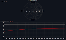
After calibration using the calibration circuits on the board (13,14,15,16) i measured all the circuits. Saved graphs of the measurements are in the table below.
I used the same graphic output for all. I know for some measurements the Smith Chart is the best output, for other other graphs are better, however this was an experiment to test and learn the VNA and compare the circuits.
| 1 | LPF-30MHz | |
| 2 | HPF-100MHz | |
| 3 | BPF-433MHz | |
| 4 | BSF-6.5MHz |  |
| 5 | 33 Ω SWR=1.5 |  |
| 6 | 75 Ω SWR=1.5 |  |
| 7 |  | |
| 8 |  | |
| 9 | ||
| 10 | ||
| 11 |  | |
| 12 |  | |
| 13 | Short |  |
| 14 | Open |  |
| 15 | Load | |
| 16 | Thru |  |
| 17 | ATT -5dB | |
| 18 | ATT -10dB |


No comments:
Post a Comment