Sunday, January 31, 2021

STM8S103F3P6 -01- Blink test

Some cheap STM8S103F3P6 Breakout Boards recently came in my mailbox from China / AliExpress and i decided that it was time to test them.

This is my first experience STM boards so i did the simple Bink test.

First i heated up my soldering iron to added some Dupont pins to 2 of this boards. At the bottom of this blogpost you see more pictures of the soldered pins  
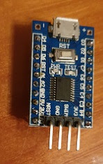
For programming a SWIM interface /  ST Link is needed. Luckily some weeks earlier a simple ST Link arrived. This was a simple PCB with an USB port and the following connections


To protect the PCB i heat-shrinked this ST Link connector.

Bottom
 [SWD]

Top
[SWIM]

3V3RST
SWD0GND
SWCLKSWIM
GND5V

With Dupont wires I made the following hardware connections between the programmer and the STM8S103F3P6 Breakout Board 

STM8S103F3P6Programmer
3V33V3
SWIMSWIM
GNDGND
NRSTRST

After configuring the Arduino IDE so that it can handle STM8  i successfully tested the board with the Blink program from the Arduino IDE (1.8.10) with the settings below.

Tools
 Board:  STM8S103F3 Breakout Board
 Programmer: ST-Link/V2

File
  Examples 
     Examples for STM8S103F3 Breakout Board
          Generic_Examples
                  01 Basics
                              Blink
               

Some links:


STM8S103F3P6 Breakout Board with Dupont pins


On one breakout board i used male ( and male pins with an angle) Dupont pins as often seen with this modules.
For the other STM8S103F3P6 breakout board i used the long Dupont pins with male and female connectors. For the SWIM interface  used male Dupont pins. I also added connectors to the + and - . The idea is that it can be easy placed in a project and the female headers still give easy access to all pins.
It is possible to use both variants on a breadboard.


Monday, January 25, 2021

Comparing two TM1638 modules

 Some year ago i also ordered another TM1638, so now i have 2 different types of TM1638 modules this blog post to compare the modules.

ModuleTM1638 LedQTF_TM1628
ConnectionPCB with Dupont connectorsPCB with dupont connectors
Posthttps://blog.jeronimus.net/2017/07/tm1638-8-bit-digital-led-module-1.html
https://blog.jeronimus.net/2021/01/qyf-tm1638-test.html
Picture
LCD display88
Led80
Dupont
Pin Arrangement
(top-down)
  • VCC
  • GND
  • STB
  • CLK
  • DIO
  • GND
  • DIO
  • CLK
  • STB
  • VCC
Buttons816
Buttons816
Buttons816

Both modules have 8 seven segment displays.
The big difference is that my first module has 8 leds and less (8) input keys, while my second module has 16 keys and no leds. As the 16 pins are arranged as 4*4 this module can be used as a Hex keypad. 
The Dupont pin arrangement on both PCBs is different.
Below schematic diagram of the modules as i did not put it in my previous posts. 


Diagrams and some other interesting info (in Italian) about these modules can be found at http://www.microcontroller.it/Tutorials/Elettronica/componenti/tm1638.htm

Sunday, January 24, 2021

QYF-TM1638 test

Tested my QYF TM1638 module with Arduino Uno

After some experimenting with my QYF-TM1628 board i got the example found at http://www.getmicros.net/arduino-qyf-tm1638-module-example.php
and arduino library at https://github.com/rjbatista/tm1638-library working.

First i tried without success another example found somewhere else on the internet. After further searching i found the example mentioned above. I had some doubt as the text in the wiring picture contained an error (two times GND at the Pinout text in the picture). I followed the wiring as displayed in the picture and the code, So my wiring was

  • Gnd – GND from Arduino
  • DIO – data pin, another ouput from your Arduino (Pin 8)
  • CLK – clock pin, an output from your Arduino (Pin 9)
  • STB – strobe pin, an output from your Arduino (Pin 10)
  • VCC – 5v from Arduino (5V)

The Dupont wire provided with the module was Female-Female, so i replaced it with female-male to connect it with an Arduino Uno. 


Example code:

#include <TM1638.h> #include <TM1638QYF.h>   TM1638QYF module(8,9,10); word mode;   unsigned long startTime;   void setup() {   startTime = millis();     module.setupDisplay(true, 7);   mode = 0; }   void update(TM1638QYF* module, word* mode) {   word buttons = module->getButtons();   unsigned long runningSecs = (millis() - startTime) / 1000;     // button pressed - change mode   if (buttons != 0) {     *mode = buttons >> 1;       if (*mode < 128) {       module->clearDisplay();       delay(100);     }   }     switch (*mode) {     case 0:       module->setDisplayToDecNumber(runningSecs, 1 << 6);       break;     case 1:       module->setDisplayToDecNumber(runningSecs, 1 << 5, false);       break;     case 2:       module->setDisplayToHexNumber(runningSecs, 1 << 4);       break;     case 4:       module->setDisplayToHexNumber(runningSecs, 1 << 3, false);       break;     case 8:       module->setDisplayToBinNumber(runningSecs, 1 << 2);       break;     case 16:       char s[9];       sprintf(s, "Secs %03d", runningSecs % 999);       module->setDisplayToString(s, 1 << 1);       break;     case 32:       if (runningSecs % 2 == 0) {         module->setDisplayToString("TM1638QY", 1);       } else {         module->setDisplayToString(String("LIBRARY "), 1);       }         break;     case 64:       module->setDisplayToError();       break;     case 128:       module->setDisplayToDecNumber(*mode, 0);       break;     case 256:       module->setDisplayToString("ABCDE", 1 << (runningSecs % 8));       break;     default:       module->setDisplayToBinNumber(buttons & 0xF, buttons >> 8);   } }

Thursday, January 21, 2021

2021 January Mailbag


 Some items in from my january 2021 mailbag from AliExpress
TM1638

QYF_TM1638

A PCB with 16 buttons and 8 seven segment displays and a driver that looks nice to use for I/O in projects e.g. with an Arduino.

10PCBs with 4 buttons

PCB with 4 Buttons

10 PCBs with 4 buttons each.
The PCBs and buttons are somewhat smaller than expected. (About 32mm*8 mm) However they are relative cheap and can be used easy in projects. Expect to use some with Dupont pins for use on a breadboard, some with wires and some direct soldered in projects. Also the next item is a reason that i did buy this cheap 4 buttons on a PCB.

433 MHz receiver / transmitter.

10 sets 433 MHz receivers and transmitters. Each set has 4 channels. I do not know if the signals interfere. It would be easy to connect one of the 4 button PCBs above with one of the 433 MHz transmitter. Where i ordered them antenna's where not included. However there are instructions how to make simple antennas for the receiver and transmitter.  I hope to find time to make an antenna set and test this item and post an update with more details on this blog.

UV Lamp

On AliExpress i also found this relative cheap 220 - 110 Volt UV Lamp. I ordered the 220Volt version without power plug and it came well packaged in foam. With a real UV lamp never radiate living tissue, your skin and take special care to protect your eyes.   I don't know if it really is an UV lamp and if it can be used for disinfection.   I have somewhere a UV detection card to test it. I decided to give it a try, perhaps it will be useful to radiate my postbag items. I did not test it yet.

Arduino CNC Shield

As i have on my long term wish list to experiment with a 3D printer / CNC machine or laser engraver i ordered this shield for an Arduino Uno. For the upcoming months i already have other plans, so this will become a long term project. However as i do not know how easy it will be in the future to get items from AliExpress i decided to already but this Arduino Uno Shield. 

 Arduino Mega and Enclosure

This two items (on one photo) where a little disappointing. It are two separate items bought from the same seller at AliExpress. On the right an Arduino Mega. On the left and middle a cheap enclodure to protect the Arduino Mega. When the enclosure came the top plate (in the middle of the photo) was not broken. This was due to my fault! I was surprised how easy it brake. I have mounted several similar enclosures for Arduino Uno's. This was the first one for Arduino Mega. The top plate from the enclosure (on the photo in the middle) dropped from table height on the floor and did brake.
Mounting of this cheap enclosure on the Chinese Arduino Mega clone was already a problem so unfortunate it was not a big loss. On this Arduino Mega the power and USB connectors are not on the exact right place so it did not fit in the holes of the enclosure. I think i will only mount the Arduino Mega on the base plate. I noticed the base plate has also holes for using it with an Arduino Uno what is a plus for this enclosure. For an Arduino Uno the holes fit exact so i expect the problem is the Arduino Mega. However i want to inform readers of this blog about the two minus points:
The top plate of the enclosure is fragile.
I think the power and USB connectors on this Arduino Mega Clone are not on the exact right position, so it does not fit in a 'standard enclosure'. 


Sunday, January 10, 2021

Big Clive Supercomputer


Some time ago the youtuber Big Clive published on his Youtube channelhis "Big Clive's SuperComputer". Several other people build their own version of this device. Some even published it on their Youtube channel. ( e.g. Julian Ilett , Learnelectronics , TheEPROM9 )
I have the parts for it, it gives a nice endresult so i decided to build one. The "Supercomputer" is a display with flashing (led)lights giving the impression of a retro computer.
I wanted to use 5 mm color leds and make it configurable, power it with  9 volt battery and use a 5*7 cm perfboard (as i have several of these boards). On the 5*7 cm board could fit 6*9 leds. However on the perfboard are only holes for 6*8. There is just one row of holes missing for nice distribution of 9 columns of leds with two open holes between each column.
I decide to put 6 rows by 9 columns anyway. I did bend the legs of the leds in the last column in a chair shape and place his leds in the last column. With the zigzag chair legs the 9 led light columns gets distributed equally.
With 6 rows of leds one row with holes is free. I used this row for Dupont male pins with jumpers. Using the jumpers it is possible to enable or disable the power to groups of leds. As i have colored jumpers i decided to use jumpers in the same color as the corresponding leds.
For selecting groups of leds any arrangement is possible. I decided to use the arrangement below:
A rectangle of red blink leds surrounded by blue blink leds and these leds surrounded by a rectangle of yellow blink leds. (R=red, B=blue, Y=yellow the number is the subgroup Jumpers are marked italic)

R1


B1

B2

B3

Y1

Y2

Y3

Y4

Y3Y2Y2Y2Y2Y2Y2Y2Y4
Y3B3B1B1B1B1B1B3Y4
Y3B3R1R1R1R1R1B3Y4
Y3B3R1R1R1R1R1B3Y4
Y3B2B2B2B2B2B2B2Y4
Y1Y1Y1Y1Y1Y1Y1Y1Y1

Using the jumpers selections of blink led can be switched on or off.
With the 8 jumpers 256 combinations can be made (including the all off or all on combination )
This selection determines which leds will be included in a random blink pattern.

To simplify the circuit as much as possible i used one  (470 ohm) resistor for all the leds.. This resulted in a failure due to the blue leds. These leds are different than the red an yellow. When much other leds where switched on the blue leds did not light up or started only blinking when the power was switched on and soon faded out. When i added a second (470 ohm) resistor for all the blue leds the "supercomputer" worked well.

After checking that everything worked as expected  i added a layer of hot glue to the back of the perfboard for protection.

Perhaps i also will post some video's on my YouTube channel of my version of this Big Clive Supercomputer. (Please post comment if you would like this)