Showing posts with label test. Show all posts

Friday, November 25, 2022

RF Testboard

To experiment with RF and a VNA a clever designed test-board kit exists so i ordered one.


https://www.sdr-kits.net/DG8SAQ-VNWA-Testboard-kit


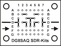
Below a description of the connections

RF testboard connections

Row A, F, G, B1 and B7 are all GND (In picture 2 presented as small circles)
Pad B4 C2 C6 E2 and E6 are Isolated (floating) pads (Not drawn in picture 2) 
The other connections between the pads are as drawn above.

Besides the PCB with the headers some jumpers and a 50 Ohm load is needed.
As a minimum it is recommended to make

2 pcs 2-pin short 
1 pcs  3 pin short
1 pcs  3 pin jumper
1 pcs 50 ohm load
Also having a 2-pin open as reference can be useful

The 50 Ohm load can be made by using 2 100 Ohm 0603 or 0805 SMD resistors in parallel (Stacked on each other). 

To make a through connection between the two SMA connectors place
2-pin shorting jumpers between D1-D2 and D6-D7 and a 3 pin jumper between D3-D5

A short or load (or open) can e.g. be made by placing appropriate components between E1 and F1

Below a picture of the kit that i did buy. It comes with the header pins and SMA connectors and 2 SMA resistors. 

I did solder the headers on the PCB and also the SMA connectors.
For the connections i first wanted to experiment with standard Dupont connectors and two "normal" 100 Ohm resistors. I know the quality would be better (and better usable at higher frequencies) if i would made it smaller, however i first wanted to get some experience and learn from the results.
I measured some of my resistors, trying to match 2 resistors to get close to 50 Ohm. However finally i just used two random selected resistors as, when measuring with my ohm meter, my 100 Ohm resistors all seemed to be just below 100 Ohm.
So i needed to use two of these resistors in parallel and the resistance would not be as close to 50 Ohm as i wanted. Using standard resistors on a normal Dupont headers would not be perfect for a 50 Ohm load anyway. To do first experiments at not to high frequencies it worked.

Monday, April 10, 2017

ESP01 Break-in board

I created several projects with EPS8266 wifi modules.
The small cheap ESP01 module has only a few IO pins so i did not used it until now.
In one of my recent Aliexpress China orders i also added a small cheap ESP01S module to my shopping list. I also ordered some boards to easy test and use of this module: ESP01 has 2x4 pins close to each other.
 Not easy to use on a breadboard therefore i also added to my shopping list.
(Right to left. [First is the ESP01 module itself] ) 
  • ESP01 - Breadboard interface. 
  • ESP01 - TTL interface
  •  ESP01 - USB interface
My plan was to use the ESP01 - USB interface board to program an test the ESP8266 module.
Then the disappointment : to program the small ESP01 module you need to pull GPIO0 to ground. My cheap interface USB module has no jumper or switch to do that!
A reset button would also be nice.
And perhaps easy access to all the pins to experiment.
If i would use the TTL interface wired this to a USB TTL / RS232 (FTDI) interface cable i would have the same problem.
An option would be start from zero, using a breadboard interface, and make my own interface.
 (Later i found there are some ESP01 USB modules with programming switch. I did not find one with programming switch and reset button!)
ESP01 with USB Module 

But what is the use of these cheap "ready to use" interfaces. For programming, testing and debugging I decided to make my "ESP01 Break-in board". A board to put between the ESP01 and the boards with the 2*4 connector.
(I decided to call it "Break in board". It is not a "Break out board" to use and get access to chip pins but a "Break in" to put between the existing connections to add features.)
It needed (minimal) a programming switch, a reset button and access to the pins.
Later on i decided to add also some additional features. (See photo, final specs/feature list below.) This are additional features but not really needed.
I used a small double Side Prototype PCB Bread board Tinned Universal 20x80 mm FR4 28*6 holes.
ESP01 "Break in board"
 with EPS and USB
connected.
 (All holes are plated through). I added pins to fit in a 2*4 pin connector (on bottom) and additional 2 times 4 pins to get easy access to all pins and a female 2*4 connector for the ESP01 module (on the top). On my (current) laptop free USB connectors are at the left side. I wired my "Break-in board" with this in mind. (USB connector pointing to the right when using this board).
Mark on the PCB with an arrow the direction of the ESP01 module.
A push button is used for the reset, (Bottom of the PCB) wired to ground and reset.
While uploading a program i do not want to continuously press a button. I decided to use a small slide switch (Top).
In stock i had a three position switch. If you have a small two position slide switch you use that. The three position switch i used has 6 pins: (and two shield pins)
Left no pins are connected
Middle pin 1 and 4 are connected ' / pin 3 and 5 connected "
Right pin 1 and 4 are connected '
Pin 2 and 6 have no use (n.c.), i did bend them away and soldered the switch on the PCB. I decided to use the middle position as programming position and wired pin 2 and 5 ' to ground and GPIO0.
3 position switch
At this point my basic minimal "ESP01 Break-in board" was ready.
ESP01 "Break in" board. (top view)
 On my board i also added some other things i had in stock:

  • 6 female pins connected to to ground (and next to it a) 
  • 25 Points Mini Solderless Prototype Tie-point Breadboard 
  • A micro switch (three pins Common, Normal open, Normal closed ) with connections to pins to easy wire them for experiments. (on bottom next to reset pushbutton).
  • Passive electromagnetic impedance 16 ohm AC buzzer/2KHz 3V 5V universal buzzer (- connected to ground, other side to a pin and 100 ohm resistor with a second pin. -
On my slide switch at pin 1 and pin 4 ' contacts available are (Left open, Middle and Right closed), i wired them to two pins on the PCB.
The condensator on the ESP01 - USB interface board comes very close to PCB. Some insulation tape was added. As a final touch i used cable ties to join some cable bundles.

ESP01 "Break in" board (bottom view)
RESULT: "ESP01 Break-in board":
Switch for programming the ESP01,
Reset button,
Easy access to all pins of the ESP01.
Some additional switches.
A mini buzzer (One side connected to ground. Connect the other side e.g. with a Dupont cable to GPIO2)
Mini solderless prototype board for additional components/experiments.
ESP01 "Break in" with ESP01 and USB (bottom view)

Wednesday, May 13, 2015

Review van mijn eerste ESP8266

In een vorige post melde ik de ontvangst van mijn pakje uit China. Ook beloofde ik een korte review van mijn ESP8266 module.
Een groot voordeel is wat je krijgt voor 4 euro: een 3x AA batterij houder, een ESP-12 gesoldeerd op een printje met spanningsregelaar, RGB led een aantal rode leds en een lichtsensor. Ook zijn alle pinnen van de ESP8266 toegankelijk.
Het bordje kan "out of the box" direct bestuurd worden via een Android app beschikbaar via de AI-Thinker website.
https://translate.google.com/translate?sl=zh-CN&tl=en&js=y&prev=_t&hl=en&ie=UTF-8&u=http%3A%2F%2Fai-thinker.com%2Fforum.php%3Fmod%3Dforumdisplay%26fid%3D40&edit-text=
Hoewel het achteraf erg simpel bleek duurde even voor ik het printje met de Android App werkend had.
Er is veel info over de ESP8266 beschikbaar over op internet. Helaas voor een groot deel in het Chinees. Ook staat de info vaak erg versnipperd.
Daarom dit recept met 5 stappen om het geheel eenvoudig werkend te krijgen:
1) Plaats het APK bestand in de Google drive van je Android telefoon.
2) Open met je Android telefoon de Google drive en kik op het APK bestand om de app te installeren.
Helaas zit de APP niet in de Google App Store maar tot mijn verrassing blijkt installeren van APK bestanden vanuit je google drive heel eenvoudig!
3) Open het draadbrugje (Draadbrug is om te flashen niet voor standaard gebruik) en plaats 3 AA batterijen.
Ja batterijen zijn in verhouding tot de electronica een grote kostenpost.)
4) Verbind je telefoon met het Wifi netwerk van je printje door het netwerk AI-THINKER_xxxxxx te kiezen met wachtwoord ai-thinker.
Ieder printje heeft een eigen netwerk beginnend met AI-THINKER_ gevolgd door een (unieke) code. Het wachtwoord is in kleine letters.
5) Start de App (helaas met Chineese interface maar de knoppen voor de Leds en RGB led zijn relatief eenvoudig te vinden).
Het is even puzzelen welke ledjes aan welke poorten zitten maar gelukkig vond ik dit plaatje op internet.
Ook verwarrend is dat de RGB led op de schuiven als op de knoppen (GPIO15=rood, GPIO13=blauw, GPIO12=groen) in de (helaas chinees-talige) app reageerd.
Achter op de printjes geschreven heb ik met een stift de AI-THINKER_xxxxxx code geschreven om ze uit elkaar te houden.
Hoe je een ander systeem in de ESP8266 kan flashen met andere firmware staat ook op diverse plaatsen (gelukkig ook in het Engels) beschreven. Voor bovenstaande test is dit nog niet nodig.
Maar om iets meer met deze module te doen wel. Helaas bevat deze module geen USB aansluiting. Voor flashen is wat extra (gelukkig goedkope) hardware nodig om de module met je computer te verbinden.

Tuesday, February 26, 2013

Publicatie op Google Play

Dit weekend de eerste versie van mijn eerste eenvoudige Android™ app geplaatst via Google Play™ :
 Android app on Google Play
Deze eerste app is voor mijn MsgServer services (gratis email, gratis URL forwarding en meer). Voor details zie de website of de app zelf.
De bovenstaande badge linkt niet rechtstreeks naar de eerste app maar naar een lijst met "alle" apps van mij. Nu (februari 2013) dus nog maar èèn, maar daar zal hopelijk binnen een paar maanden verandering in gekomen zijn.
Maar daarnaast ook nog andere belangrijke activiteiten dus kan helaas niet beloven dat ik er voldoende tijd aan kan geven!

Heb wel nieuwere versies en nog andere app's op de plank liggen maar die wil ik nu nog niet direct publiek zetten. Eerst maar eens een klein begin en het publicatie proces uitproberen met een eenvoudige eerste versie.
De hele publicatie was een leerzaam proces waarbij het wel even spannend was want het duurde ook even voor de app overal zichtbaar werd.
Naast het maken van de app zelf kost ook het maken van de benodigde plaatjes en begeleidende tekst best tijd.

Als een wat uitgebreidere versie van mijn app gepubliceerd is wil ik dit ook weer hier op mijn blog vermelden. Dan wel met een link naar de app zelf.
Verder heb ik nog wat ideeën die nog verder uitgewerkt moeten worden voor andere app's dus kijk regelmatig!

Eerste begin is er:
Mijn eerste publicatie op
Google Play™ is een feit!


Thursday, July 17, 2008

Proef2

Met blog.press kan remote wat worden toegevoegd

Test-blogpost1

Blog This - simple editor using the Blogger JavaScript API

Test this now