Showing posts with label RFID. Show all posts

Thursday, May 25, 2023

Niimbot D110

What is a Niimbot D110? It is nót a kind of robot. It is not related to a Nimbus 2000 from Harry Potters magical world. It is small, light, not to expensive and it can help in organizing things. It is a relative cheap thermal label printer. When i did see the price i knew this is not something to put my whish list and wait.  This is something i need to buy now especially as i am reorganizing my workshop.
However before placing the order i did watch several Youtube videos and i also installed the Niimbot app to test the software. 
One day after placing my order the playstore requested me to update the software and a short time later a second update for the app.. After this two updates i did try the software again and at that moment i had doubts if i was happy with my order. This as the software did not work anymore. I didn't know if this was due to the fact that i had no Niimbot connected or if the software had a bug. I could till cancel my order easy as it was not shipped yet, however i decided to wait. This as i probably would not be the only one with this problem and if the printer did not work at arrival i could return it anyway. The printer arrived relative fast and luckely another app update came before the printer arrived and it worked all fine.
The Niimbot D110, a small thermal label printer can only print black and the current price is just above 20 euro's including one label roll I think the low price if for two main reasons: 
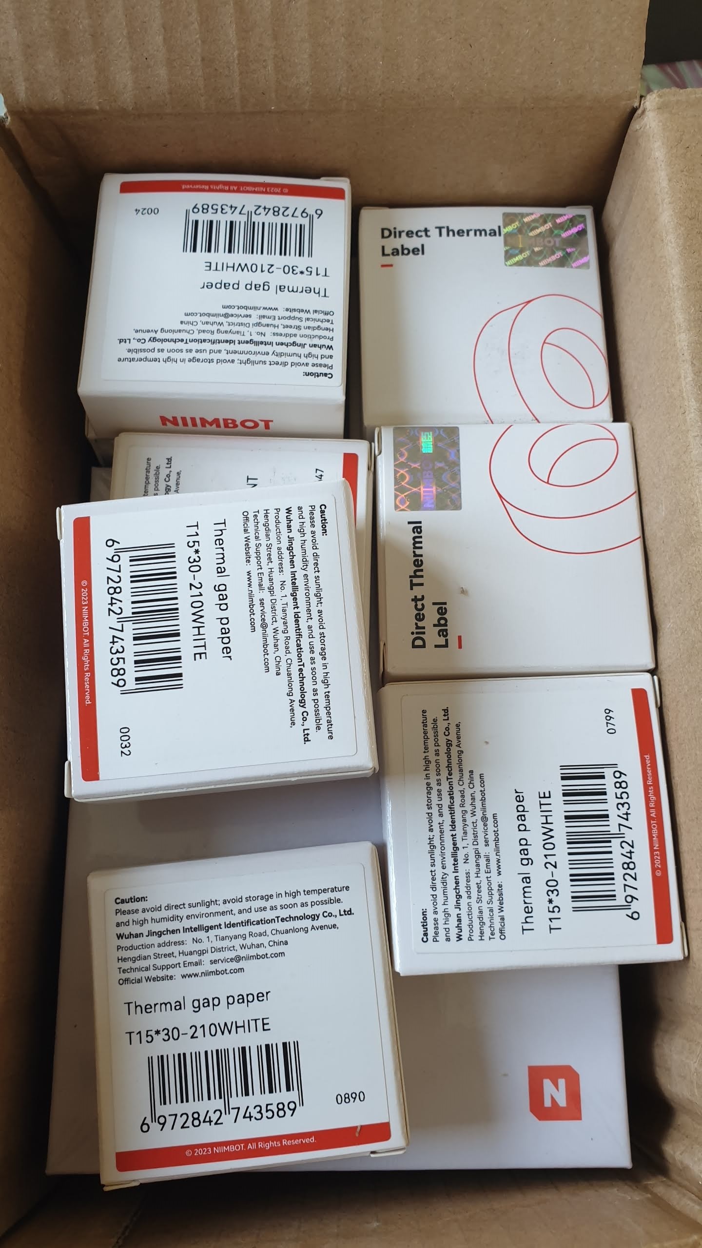
1) Only Niimbot thermal labels can be used. The labels on the roll are not cut by the label printer and have fixed sizes. There are many different labels available, different sizes and also labels with colors and printed colored figures. 
2) The device itself has not much controls, only one switch with an led and you need to control it via a smartphone app using bluetooth. 
The app if free and in several app-stores. It contains a label editor and it is possible to print barcodes, QRcodes, using several fonts and font sizes, change direction or the content, and a use library with pictures and icons. You can also take pictures with your smartphone or use images to put on your label (no colors, only black). Importing a (small) Excel file to print a series of labels is also possible however i didn't try this yet.
More fonts and icons are in the payed VIP version of the app for a monthly. I found the VIP functionalities not sufficient interesting for its price and for normal use this is not needed.
When writing this review I already started labeling my inventory. The app to design the labels and the printer work very wel and i am happy with my Niimbot D110. I did buy a set that came with more rolls of labels. Also i did buy some transparent labels. (I did pay it for myself so this is not an advertorial or sponsored message!)
It is possible to buy labels in packs of 3 5 or 6 to get a better pice. I did not yet buy or tried other kind of labels. The label roll contains an RFID chip so the printer (and your app) knows which labels are currently in the printer. I already have an empty label roll and kept it to perhaps play with it using an RFID reader.
Changing labels is relative simple. However the first label after changing will probably not be alligned correct. Do not open the printer to fix this. The second label will be correct automatic. 
I will mention now some little things that could be improved / added to the app to make it even more usefull:
1) Exporting the print history is not possible. When you could export the print history e.g. to Excel you could get a complete list of your inventory after labeling. (You can import excel to make labels, however when inventarizing it is more easy to be on location, create a label on your phone, print it and stick it immediate on the item that to create a list in excel, print labels and match label per label with the item.)
2) Missing icons. There are several nice icons already in the app and een more in the payed VIP version.  However i do miss icons for standard hardware (diffent kind of bolts and nuts, flat/round top, to be used with normal, phillips screwdriver or special bits) that you can find in almost every home. Also icons for electronic components would be a nice addition. (Diodes, transistors, ICs, resistors, capacitors, leds etc.). I know the last set (electronic components) is perhaps somewhat specialistic. Standard hardware (nuts and bolts) is relative general. This would for me be more usefull than e.g. the icons for gardening.
It is possible to make this images yourself and use them with the printer, however i did not do this (yet). It would be nice if this where standard included icons. I did take some photo's of items to put it on a label. As far as i could see, even in the payed VIP version electronic of nuts and bolt icons are not available.

Friday, May 19, 2023

Inventory system part 2 – tools to use for NFC and QR

 As type NFC tag I selected round NTAG213 stickers. I experimented already with these tags. They have sufficient capacity for this applications, are easy to attach and also can be ordered easy (Aliexpress).

I have a lot of A4 printer labels 7cm x 2.5cm (3 columns 10 rows) and I wanted to use them also.

I like a relative big QR code and also a storage number written in digits. On small storage drawers a 7cm*2.5cm label is too big. So I decided to print text for two labels on one label and after printing cut the 7cm in 2x3.5cm. So in theory fit 6columns and 10 rows = 60 labels on one A4. Unfortunately I could not easy fill the complete A4 width. There missed a little piece of the QR code in the last column. So I decided to not use the last column and print 5 columns each 3.5 cm x 2.5 cm and discard the last 3.5 cm column. On small drawers I did put the label with the QR and number in readable format on the backside. At the front I want a small label with the content as text (and perhaps a small QR code).

It is possible to create QR codes that direct link to a webpage with the ID on the tag in the URL. However I decided not to do that and create a QR code that only gives the number.

To use NFC tags and QR code some tools are needed. I can build something to read and write NFC tags with a microcontroller like Arduino or ESP32. As my android smartphone as this is most times already available, using my phone is preferred.

For NFC tags several apps are available in the app-store(s). One app that draw my attentions and is Scan-it to office. With this app you can read an NFC tags, read a QR code, take a pictures, enter some text, and do several things more. The scan results can end up in a Google spreadsheet, a word or excel document, a database, a webform (using chrome browser) or are send to your (Windows or Apple) computer as if you entered the data using your keyboard. The free “demo” version that, at random intervals, does not send the captured data but a message. A paid version that doesn’t has this limitation costs (at the moment) less than 4 euros for one month for one smartphone. A three months or a year subscription gives discount and there is also a licence for use on multiple smartphones (e.g. for a company). A review and more details about Scan-it to office will be presented in a separate blog post. As already mentioned I will write on my blog also about some other NFC apps and what they can do.

To bulk print labels with QR code and a number, using my 7cm x 2.5cm (3 columns 10 rows) labels on A4 works good. Creating small labels describing the content of small drawers is a bit more difficult as you can only print a lot of labels at the same time, and after that you need to sort out on which drawer to put which label. There are now relative cheap small label printers available that can print directly from a smartphone app. I ordered one to check if this can help me with my inventory system.

So currently a lot of material that can be used for my blog posts even when I have not much time for real electronic projects. 

Tuesday, May 16, 2023

Inventory system part 1 - using NFC and QR (intro)

 I like #NFC / RFIDtags. ( RFID stands for Radio Frequency Identification, a contactless one-way communication method at varying distances. NFC, Near Field Communication, allows for two-way communication and  requires action by the user.)

You can read and write to NFC tags with a special reader/writer(/or clone) device, a NFC smartphone (most modern smartphones do have NFC) or using a microcontroller like ESP32 or Arduino using a cheap NFC interface. 

Especially the NTAG213 tags are very nice and are in bulk relative cheap available as stickers that can be used for labelling inventory.  The NTAG213 even has a built in counter that, in enabled, counts how many times you did scan the tag.  (For my last order in China of NTAG213 stickers I did pay EURO 11.83 for 100 pcs). 

Normal stickers with QC or bar code are cheaper. NFC stickers have the advantage that you can also write and modify information on it however labelling everything with NFC would be more expensive. 

When printing a QR or barcode you can at the same time print a numerical or text value for easy identification without using a device.

With a cheap NFC reader connected to an Arduino you can change the bytes on the NFC tag. However I also want to use my smartphone. I have some NFC apps on my smartphone. Reading or changing individual bits is not always possible with every android apps.

Therefore in one of my next blog posts I will describe some of the NFC apps on my phone with features and also some details about the NTAG213 .

Currently I am reorganizing all my electronics material due to a major change of my workshop. That is also the reason why i current publish less projects. However this is also the reason you will see some posts about topics related to this reorganizing. For my storage system there have some must haves and some wishes.

  • It needs to be a big improvement to the current situation
  • I want more standardization in my boxes (not a lot of different sized boxes with components that are difficult to stack…)
  • It must have an overview and searchable lists of components (in a computer system)
  • It needs to be extreme flexible and easy to adapt, maintain and correct
  • It may have (some) redundancy
  • I want to have more than just labels with some text my boxes. I like to experiment with things like NFC tags and QR codes for easy interfacing. However at the moment also OCR is relative good and can be uses.
  • It must be not too expensive

As I want it to be not too expensive it will not be possible to put NFC tags on everything. NFC are not extreme expensive however still cost more than 10 cents per tag and a QR code printed on a label is cheaper. Due to the kind, the amount and diversity of items I want to store the storage easy can become expensive compared to the price of the items.  However I want to use NFC tags on some items and put QR codes on every storage location (also on the locations where I did put an NFC tag.

On some drawers, boxes and more expensive items I did put a NFC tag and a QR code with an unique number. On small drawers and boxes for nuts, bolts and electronic components I did put only a QR code. The QR codes contains the number. In a follow-up post I will describe the numbering system I used. The NFC tag - number / QR code only indicate a storage location. The storage location is a “container” that can have  items inside. What is in a “container” can be indicated on a separate label on the “container”. A “container” (or “container” ID) is not a real indication where exactly an item is as e.g. the location of two component drawers may be swapped (intentionally or by accident). It is only an indication in which “container” the item is.

I want my storage system robust enough to handle swapping/changing the locations of “container”. So all my components will be inside unique numbered “containers”. A “container” can also be inside another “container”, sometimes together with other “containers” and other items. (E.g. a box can be in a drawer.) I hope this will give sufficient flexibility to store (and find) my components.


Thursday, May 14, 2020

Dual frequency RFID reader -2-

To test my dual frequency RFID reader added some Dupont connectors on the other side of the provided cable.
To make easy changes i decided to add one pin connectors to all the wires. All cables have different colors, however i also wanted to put them quick in the same order as on the connector. So i put all the wires in the right order through an 8 pin Dupont housing. The plastic 8 pin housing can be put on any position as it can move free and is only for quick putting the wires in the right order.
(In fact it is a complete Dupont housing, i did cut of a small part of the housing where the holes for the wires are smaller.)
Hope this little hack will prevent mixing up the wires.
I already did a quick test of the Led with a small 1.5V coin cell. When putting the 1.5V coin cell directly on the leads of the led it lights up. Connecting 1.5V to combinations of wires like VCC (Red),  LED (Orange) and GND (Black) did not light the led.
A next step will be testing the RFID sensors, the led and buzzer. For the final part i need to decide if i will use an Arduino or an ESP module and where exactly i want to place this reader.

Tuesday, May 12, 2020

Dual frequency RFID reader -1-

For RFID experiments i also have a cheap dual frequency RFID reader with enclosure from my old mailbag. Bottom side of the enclosure is open. The size is about 7,5cm * 11,5 cm. A resin protects the components and a connector with wires (30 cm) is included.
It contains not only a 25Khz and 13.56MHZ  RFID reader. Also a led and buzzer is inside this enclosure.
For the RC522 RDIF reader there are several examples on the internet. For this reader i did not yet find much instructions. Also i and did not yet test the module.

Website of manufacturer ( Chinese)
https://gwiot.com/

Website with use example (Only RFID not using buzzer or led test)
https://smartpoker.jimdofree.com/modules-rfid/lecteur-rfid-7304d2/
The page contains links for code and more info to


Additional info on this page
https://world.taobao.com/item/45234761820.htm
Google translation of some text on this page about temperature sensibility
Special Note
     1. If the product with a temperature resistance of 60 degrees is placed in the gate, the direct sunlight at noon in summer will seriously affect the IC card reading function. The product with a temperature resistance of 80 degrees can work stably.
     2. The sensitivity of card swiping of temperature-resistant 80-degree products is higher than that of 60-degree products.
     3. It is recommended to use the pedestrian gate only, which has good adaptability to the metal environment.
    4. The default stock color of the product is carbon black. If you need white, please communicate with customer service if there is stock.
  5. The temperature-resistant 60-degree dual-frequency read head has been discontinued and needs to be ordered.
Due to the (poor translated) text above i expect better to keep the module out of direct sunlight if possible.

According the internet the following cards can be used:

 13.56MHZ /
 ISO14443 TYPE A

  1. NXP_Mifare1k
  2. NXP_Mifare4k
  3. NXP_Mifare mini
  4. Ultralight (C)
  5. Mifare  PlusX(S)
  6. Desfire  D21  D41  D81 
  7. NTAG203(F)
 125KHZ
  1. EM4100
  2. EM4200
  3. JT120 (??)

A Chinese mini manual was included when delivered from AliExpress. In this first post about this module only some info, pictures and a first try to translate the manual using google translate. Hope it will be soon possible to make a next post about this module with some results.

Friday, December 13, 2019

Business Card PLUS (#002)

PCB Business Cards
Yesterday I posted a short quick message on my blog to show my Business Card PLUS have arrived.
I decided that my (classic) Business Card needed an update. I still have several of this paper business cards. As the information on them is still up to date i don't like to throw them away as waste. So will still use them but, if i become more happy with the Printed Circuit Board  - Business Cards i expect not to order new paper cards. I wanted a business card that can be used.
The price of manufacturing this PCBs in China is low. To get PCBs in low quantities relative cheap best stay under the size of 100 mm * 100 mm and the minimum order is 5 pieces. By "panelizing" the PCB you can even get more PCBs. I don't like to throw away unused PCB's. Perhaps if i need a PCB for future project perhaps i will design them so the PCB can also be used as a business card.
However a few weeks ago i started designing a (test) PCB especially to be used as a business card.
'classic' Business Card
Panelizeing the PCBs gave multiple PCBs with a break line for easy separation. As the manufacturer needs to add some text to your PCB to identify the order between all other orders i a added borders and asked the manufactured to place there ID on the boarder. I even changed the size of the PCBs a little from the standard size. This way two PCB/Business cards can be placed on one 100*100 mm PCB. As the minimum order is 5 (< 100*100 mm) PCB you will get after separating them 10 cards. ( In fact 10 panelized PCBs where ordered ,so i now have have 20 new business cards / PCBs that can be used different ways.
The disadvantage of my new card is that it is not possible to write something on the back.As i also have plans to add RFID with a sticker (also usable with classic paper business card) this can change).
To quick start, this first PCBs contain no QR. code. However i did add a ruler to the design.
The PCB can be used for electronic circuits in different ways. On my blog i will post some examples with test results and hope it will work in this first batch of PCBs. If not i can still use this batch as 'regular' business cards. If you get one of my PCB business cards and want to dispose it, consider giving it to someone else who perhaps can use it.
Also i would be happy to know how my PCB business cards are used (or only the [complex] PCB). Comments on this blog, mail, about this topic is welcome. I will share the Gerber files so you can (adapt and) order your own PCB if you don't get one from me. New blog post about this PCB will be published soon.


Thursday, March 29, 2018

RFID and Wemos D1 mini (1)

I wanted to connect an RFID reader to my home network.
Therefore i used a ESP8266, more specific the Wemos D1 mini Wifi module.

Test 1 (fail)

I found a project on http://www.instructables.com/id/WiFi-RFID-Reader/ using a Wemos D1 mini. The exact info about the pins was missing.
As a test i created the circuit as a test on a breadboard using the Wemos D1 mini pin info on https://escapequotes.net/esp8266-wemos-d1-mini-pins-and-diagram/. (See also this picture with Wemos D1 mini connections)


RFIDESP8266Wemos D1 mini
RSTGPIO05 (free GPIO)D1
SSGPIO4 (free GPIO)D2
MOSIGPIO13 (HW SPI)D7
MISOGPIO12 (HW SPI)D6
SCKGPIO14 (HW SPI)D5
GNDGNDG
3.3V3.3V3V3
The instructional also contains software to read basic RFID info and send it over the serial (usb) line.

define RFID module

#include "MFRC522.h"
#define RST_PIN 15 // RST-PIN for RC522 - RFID - SPI - Modul GPIO15 
#define SS_PIN  2  // SDA-PIN for RC522 - RFID - SPI - Modul GPIO2
MFRC522 mfrc522(SS_PIN, RST_PIN);   // Create MFRC522 instance

Initialize RFID module

void setup() {
  Serial.begin(9600);    // Initialize serial communications
  SPI.begin();           // Init SPI bus
  mfrc522.PCD_Init();    // Init MFRC522 
}

Read RFID tag

void loop() { 
  // Look for new cards
  if ( ! mfrc522.PICC_IsNewCardPresent()) {
    delay(50);
    return;
  }
  // Select one of the cards
  if ( ! mfrc522.PICC_ReadCardSerial()) {
    delay(50);
    return;
  }
  // Show some details of the PICC (that is: the tag/card)
  Serial.print(F("Card UID:"));
  dump_byte_array(mfrc522.uid.uidByte, mfrc522.uid.size);
  Serial.println();
}

// Helper routine to dump a byte array as hex values to Serial
void dump_byte_array(byte *buffer, byte bufferSize) {
  for (byte i = 0; i < bufferSize; i++) {
    Serial.print(buffer[i] < 0x10 ? " 0" : " ");
    Serial.print(buffer[i], HEX);
  }
}
Unfortunate the example above did not working for me. I got output on the terminal, however there was a message about perhaps bad connections.

Test 2 (succes)

More succesfull was the next example that  i found this on github:
https://github.com/Jorgen-VikingGod/ESP8266-MFRC522

Wiring RFID RC522 module

The following table shows the typical pin layout used:
SignalMFRC522WeMos D1 miniNodeMcuGeneric
RST/ResetRSTD3 [1]D3 [1]GPIO-0 [1]
SPI SSSDA [3]D8 [2]D8 [2]GPIO-15 [2]
SPI MOSIMOSID7D7GPIO-13
SPI MISOMISOD6D6GPIO-12
SPI SCKSCKD5D5GPIO-14
  • [1] (1, 2) Configurable, typically defined as RST_PIN in sketch/program.
  • [2] (1, 2) Configurable, typically defined as SS_PIN in sketch/program.
  • [3] The SDA pin might be labeled SS on some/older MFRC522 boards (including the one i used)

Define RFID module

#include "MFRC522.h"
#define RST_PIN 5 // RST-PIN for RC522 - RFID - SPI - Modul GPIO5 
#define SS_PIN 4 // SDA-PIN for RC522 - RFID - SPI - Modul GPIO4 
MFRC522 mfrc522(SS_PIN, RST_PIN); // Create MFRC522 instance

Initialize RFID module

void setup() {
  Serial.begin(115200);    // Initialize serial communications
  SPI.begin();          // Init SPI bus
  mfrc522.PCD_Init();    // Init MFRC522
}

Read RFID tags

void loop() { 
  // Look for new cards
  if ( ! mfrc522.PICC_IsNewCardPresent()) {
    delay(50);
    return;
  }
  // Select one of the cards
  if ( ! mfrc522.PICC_ReadCardSerial()) {
    delay(50);
    return;
  }
  // Show some details of the PICC (that is: the tag/card)
  Serial.print(F("Card UID:"));
  dump_byte_array(mfrc522.uid.uidByte, mfrc522.uid.size);
  Serial.println();
}

// Helper routine to dump a byte array as hex values to Serial
void dump_byte_array(byte *buffer, byte bufferSize) {
  for (byte i = 0; i < bufferSize; i++) {
    Serial.print(buffer[i] < 0x10 ? " 0" : " ");
    Serial.print(buffer[i], HEX);
  }
}
THis did work and i expected that was a good starting point for the rest of my project.