Showing posts with label SMD. Show all posts

Friday, November 25, 2022

RF Testboard

To experiment with RF and a VNA a clever designed test-board kit exists so i ordered one.


https://www.sdr-kits.net/DG8SAQ-VNWA-Testboard-kit


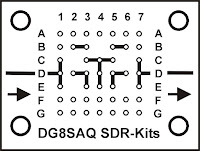
Below a description of the connections

RF testboard connections

Row A, F, G, B1 and B7 are all GND (In picture 2 presented as small circles)
Pad B4 C2 C6 E2 and E6 are Isolated (floating) pads (Not drawn in picture 2) 
The other connections between the pads are as drawn above.

Besides the PCB with the headers some jumpers and a 50 Ohm load is needed.
As a minimum it is recommended to make

2 pcs 2-pin short 
1 pcs  3 pin short
1 pcs  3 pin jumper
1 pcs 50 ohm load
Also having a 2-pin open as reference can be useful

The 50 Ohm load can be made by using 2 100 Ohm 0603 or 0805 SMD resistors in parallel (Stacked on each other). 

To make a through connection between the two SMA connectors place
2-pin shorting jumpers between D1-D2 and D6-D7 and a 3 pin jumper between D3-D5

A short or load (or open) can e.g. be made by placing appropriate components between E1 and F1

Below a picture of the kit that i did buy. It comes with the header pins and SMA connectors and 2 SMA resistors. 

I did solder the headers on the PCB and also the SMA connectors.
For the connections i first wanted to experiment with standard Dupont connectors and two "normal" 100 Ohm resistors. I know the quality would be better (and better usable at higher frequencies) if i would made it smaller, however i first wanted to get some experience and learn from the results.
I measured some of my resistors, trying to match 2 resistors to get close to 50 Ohm. However finally i just used two random selected resistors as, when measuring with my ohm meter, my 100 Ohm resistors all seemed to be just below 100 Ohm.
So i needed to use two of these resistors in parallel and the resistance would not be as close to 50 Ohm as i wanted. Using standard resistors on a normal Dupont headers would not be perfect for a 50 Ohm load anyway. To do first experiments at not to high frequencies it worked.

Wednesday, September 21, 2022

Audio transformer - breadboard friendly

Some time ago i ordered some cheap 600:600 ohm audio transformers to use them for some experiments. To easy wiring up an experiment it is possible to plug a transformer direct in a breadboard. The audio transformers fit exactly in a 3*4 grid on a breadboard. (With normal mains transformers I would not recommend this as i don't think it is safe to use high voltages or mains on a breadboard.)
I liked to make a more breadboard friendly version to handle the little transformer more easy, make it easy to move the transformer to other places on the breadboard and have the connections always at the same distances and also get somewhat more robust pins.

 A special PCB for the transformer could have been created, however i still had some 8 pin SMD PCBs and i realized they can be easy adapted for this transformers. This are small PCBs, normally used for 8 pin SMD ICs to making through hole compatible (or make them usable on a breadboard).

At the copper connections for the 8 pin SMD IC some connections were made:  pin 1 to 2 , 3 to 4 , 5 to 6 and 7 to 8. A small wire with some solder to bridge the gaps was used as solder alone tended to flow back on the pads. When you want a connection it sometimes does not work and when you don't want a connection.... 
The wires of the audio transformer fit exactly as 3*4 grid in pin holes 2, 4, 5, and 7. However first the Dupont male pins at pin 1, 8, 3 and 6 (see photos) were soldered as soldering the transformer first would make it more difficult.
For stability 2 strips with 4 male Dupont pins were used, first removing the middle 2 pins as they are not needed.  
1234


8765
The green positions are wires for the audio transformer and at the red positions are for the Dupont pins.  As there are connections between pin 1-2 , 3-4 , 5-6 and 7-8 the transformer is now breadboard friendly.
(Picture with breadboard, a breadboard friendly and a direct plugged in audio transformer and some other components)

Sunday, December 15, 2019

SMD Leds breadboard friendly -2-

Mailbag
August 2019 i published how to make SMD leds breadboard friendly with Dupont connectors.  https://blog.jeronimus.net/2019/08/smd-led-breadboard-friendly.html

Another option to make SMD components more breadboard friendly is to using a PCB. I found some SMD PCBs on Aliexpress and ordered 3 lots with 10 PCBs. (30 PCBs in total)
The PCBs arrived some days later in my mail in a small envelope. See "Mailbag" picture on the right. They match DIP 8 format and you need to break them apart yourself.
Besides for DIP 8 IC's these PCBs can also be used for other SMD components.
For a test I soldered some different SMD leds on them. To solder the Dupont pins to the PCB i used a small breadboard to temporary fix the Dupont pins at the right positions.


Wednesday, August 14, 2019

SMD led breadboard friendly.

I wanted to do some easy prototyping with SMD leds (and other components).
SMD components are available in different (small) sizes.
One of the ways I made the SMD leds breadboard friendly is as follows:

1) Put an SMD led and a long Dupont pin connector on your workbench,
2) If the SMD led is somewhat bigger remove a pin (the second pin) from the connector.
3) Tin the Dupont connector where it needs to be connected to the led.
4) Push the Dupont connector on the led and solder by heating the connector. If needed add a little solder.
5) Cut the connector on the desired size (2 or '3' ) pin.
6) Test the led and the connections using a led tester.

By cutting the connector after soldering it is more easy to push the connector on the led and making the solder join.

On the picture you see at the left some end results and at the right a "standard" red led as size reference.
On the bottom left a " big" SMD led with a Dupont connector with the middle male pin removed.
The other 3 SMD leds are smaller leds that fit on two pins.

Tuesday, July 16, 2019

SMD project

To get more experience with SMD soldering i build this led chaser.
The circuit of this running light consists of a 555 timer to make pulses
 and a 4017 counter. Both ICs are SMD and also the two condensators C1 and C2 and the other 12 resistors.
The photo below shows the difference is size of a "standard" resistor and an SMD resistor.here are also small SMD leds, however "standard" red led lights are used.
To my surprise the SMD intergrated circuits where more easy to solder than the resistors and condensators.
I used a soldering iron, flux pen, tweezers and a magnifier glass.
The video shows the working circuit. As you can see the  wires of the leds are not cut off as i wanted to attach Dupont connectors to do some more experiments with this small cheap Aliexpress DIY circuit.