Showing posts with label STM8S103F3P6. Show all posts

Monday, February 1, 2021

STM8S207 / 103 board "Clock LEDs"

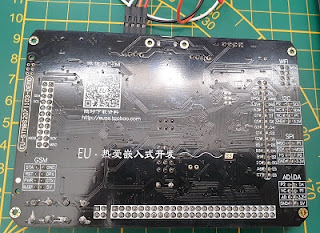
On AliExpress i also ordered the  EU-STM8S207|103-DEMO board.

This board has two STM8 controllers and several hardware items.
According to info the two STM8 controlers should be able to communicate with each other.
There is a MicroSD card holder, a W2064 Flash ram, A buzzer (Beep), LDR, One reset button. Two buttons connected to the 207 and one button connected to the 103 (on which pin??), Several connectors (e.g. for ESP01 wifi),GSM. SPI, I2C AD/DA, GDM, 207-UART1 a 207-SWIM and 103-SWIM and some other items. Also additional boards to add more hardware can be ordered.

Unfortunately i could not yet find good documentation or a schematic diagram.

After playing with a cheap STM8S103F3P6 board i decided to try out this board and connected my ST-link (shown in an earlier post) to the 103-SWIM connector. On this board the SWIM connector indicates 5V so i used 5V.  ( The STM8S103F3P6 board indicates 3V3 so there i used 3V3).

I modified the STM8S Blink sketch to the sketch below to test the output pins.

// CODE

const int LED_TT = 12;

/
 pinMode(LED_TT, OUTPUT);
}

// the loop function runs over and over again forever

void loop() {

  digitalWrite(LED_TT, HIGH);   // turn the LED on (HIGH is the voltage level)

  delay(1000);                       // wait for a second

  digitalWrite(LED_TT, LOW);    // turn the LED off by making the voltage LOW

  delay(1000);                       // wait for a second

}

// END CODE

LED_TT is Led To Test
By changing the LED_TT value in the program above i could test the "Clock like arranged Leds".

Results are in the table below.

Clockwise 1-12
LEDs on PCB
Pin in
Script
10
21
32
44
53
65
76
87
88
109
1111
1212

Strange that the 4 and 3 are swapped. I expect Pin 10 (D10) is not used as this corresponds to SWIM in some pictures i found.


Sunday, January 31, 2021

STM8S103F3P6 -01- Blink test

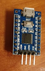
Some cheap STM8S103F3P6 Breakout Boards recently came in my mailbox from China / AliExpress and i decided that it was time to test them.

This is my first experience STM boards so i did the simple Bink test.

First i heated up my soldering iron to added some Dupont pins to 2 of this boards. At the bottom of this blogpost you see more pictures of the soldered pins  
For programming a SWIM interface /  ST Link is needed. Luckily some weeks earlier a simple ST Link arrived. This was a simple PCB with an USB port and the following connections


To protect the PCB i heat-shrinked this ST Link connector.

Bottom
 [SWD]

Top
[SWIM]

3V3RST
SWD0GND
SWCLKSWIM
GND5V

With Dupont wires I made the following hardware connections between the programmer and the STM8S103F3P6 Breakout Board 

STM8S103F3P6Programmer
3V33V3
SWIMSWIM
GNDGND
NRSTRST

After configuring the Arduino IDE so that it can handle STM8  i successfully tested the board with the Blink program from the Arduino IDE (1.8.10) with the settings below.

Tools
 Board:  STM8S103F3 Breakout Board
 Programmer: ST-Link/V2

File
  Examples 
     Examples for STM8S103F3 Breakout Board
          Generic_Examples
                  01 Basics
                              Blink
               

Some links:


STM8S103F3P6 Breakout Board with Dupont pins


On one breakout board i used male ( and male pins with an angle) Dupont pins as often seen with this modules.
For the other STM8S103F3P6 breakout board i used the long Dupont pins with male and female connectors. For the SWIM interface  used male Dupont pins. I also added connectors to the + and - . The idea is that it can be easy placed in a project and the female headers still give easy access to all pins.
It is possible to use both variants on a breadboard.