Showing posts with label 37in1SensorKit. Show all posts

Friday, September 9, 2016

Arduino_KY-015_Temperature_and_humidity_sensor_module

KY-015 37-1 Temperature and humidity sensor module (DHT11)

Hardware

Connections between the Arduino for this temperature and humidity sensor from the 37in1 sensor kit with the KY-015 DHT11 module
  • Arduino pin 8 --> Pin S module
  • Arduino GND --> Pin - module
  • Arduino +5    --> Pin Middle

Program

The temperature and humidity values are displayed on the Serial monitor (To use the Codebender Serial monitor you need to connect it !)

Serial monitor


More info


// ** Arduino KY-015 Temperature and humidity sensor module ** /* ** HARDWARE Arduino pin 8 --> Pin S module Arduino GND --> Pin - module Arduino +5 --> Pin Middle DHT11 Temperature and humidity sensor */ int DHpin = 8; byte dat [5]; byte read_data () { byte data; for (int i = 0; i < 8; i ++) { if (digitalRead (DHpin) == LOW) { while (digitalRead (DHpin) == LOW); // wait for 50us delayMicroseconds (30); // determine the duration of the high level to determine the data is '0 'or '1' if (digitalRead (DHpin) == HIGH) data |= (1 << (7 - i)); // high front and low in the post while (digitalRead (DHpin) == HIGH); // data '1 ', wait for the next one receiver } } return data; } void start_test () { digitalWrite (DHpin, LOW); // bus down, send start signal delay (30); // delay greater than 18ms, so DHT11 start signal can be detected digitalWrite (DHpin, HIGH); delayMicroseconds (40); // Wait for DHT11 response pinMode (DHpin, INPUT); while (digitalRead (DHpin) == HIGH); delayMicroseconds (80); // DHT11 response, pulled the bus 80us if (digitalRead (DHpin) == LOW); delayMicroseconds (80); // DHT11 80us after the bus pulled to start sending data for (int i = 0; i < 4; i ++) // receive temperature and humidity data, the parity bit is not considered dat[i] = read_data (); pinMode (DHpin, OUTPUT); digitalWrite (DHpin, HIGH); // send data once after releasing the bus, wait for the host to open the next Start signal } // *** SETUP *** void setup () { Serial.begin (9600); pinMode (DHpin, OUTPUT); } // *** LOOP *** void loop () { start_test (); Serial.print ("Current humdity ="); Serial.print (dat [0], DEC); // display the humidity-bit integer; Serial.print ('.'); Serial.print (dat [1], DEC); // display the humidity decimal places; Serial.println ('%'); Serial.print ("Current temperature ="); Serial.print (dat [2], DEC); // display the temperature of integer bits; Serial.print ('.'); Serial.print (dat [3], DEC); // display the temperature of decimal places; Serial.println ('C'); delay (700); }

Wednesday, September 7, 2016

Arduino_KY-017_Mercury_open_optical_module

Arduino KY-017 Mercury open optical module

Mercury tilt switch that allows you to detect the tilt of your object.
Module also contains a status led.
One bad thing about this module is the toxic mercury.
As long as the glass bulb is closed it will give no problems.
This module needs to be disposed as toxic waste !

Hardware

  • S           Arduino Pin 3
  • middle   +5V
  • -           GND

Function

Arduino led (Pin 13) displays tilt status.

More info

Program

// ** Arduino KY-017 Mercury open optical module ** /* ** HARDWARE ** S Pin 3 middle +5V - GNF int buttonpin = 3; // define the mercury tilt switch sensor interface int Led = 13 ; // define LED Interface int val ; // define numeric variables val // *** SETUP *** void setup () { pinMode (Led, OUTPUT) ; // define LED as output interface pinMode (buttonpin, INPUT) ; // define the mercury tilt switch sensor output interface } // *** LOOP *** void loop () { val = digitalRead (buttonpin) ; // read the values assigned to the digital interface 3 val if (val == HIGH) // When the mercury tilt switch sensor detects a signal, LED flashes { digitalWrite (Led, HIGH); } else { digitalWrite (Led, LOW); } }

Tuesday, August 30, 2016

Arduino_KY-018_Photo_resistor_module

Arduino KY-018 Photo resistor module

Photo resistor 37in1 sensor KY-018 tested with Arduino

Hardware connections

  • Module Signal (S)  -  Arduino A5  (analog in) 
  • Module +5V (Pin2) -  Arduino 5V 
  • Module GND          - Arduino GND

Program

The program below reads the analog signal and outputs it to the serial monitor..
Open serial monitor to see the values.

Console


Links

https://tkkrlab.nl/wiki/Arduino_KY-018_Photo_resistor_module


Friday, August 26, 2016

Arduino_KY-009_3-color_full-color_LED_SMD_module_NotWorking

KY-009 37-1 3-color full-color LED SMD module

Some versions do contain additional resistors on the module. However some versions don't. In that case
 additional resistors are needed
On the internet i found examples with

  • 2 x 100 Ohm and one 180 Ohm, 
  • 3x 390 Ohm 
  • 3x 220 Ohm.

The pin layout can also be different.
My module contains the text  cnt1 / Keys / 3_Clor and -GRB is printed as pin layout and contains no additional resistors on the PCB. ( cnt1 in small letters) I also have seen variants with CNT1 in big letters and -RGB
I tried my RGB led module (after adding the additional Resistors) but i did not get my module working !

Hardware

  • Arduino pin 11 --> 100 Ohm resistor --> Pin 'B' of KY-009 module
  • Arduino pin 9   --> 180 Ohm resistor --> Pin 'R' of KY-009 module
  • Arduino pin 10 --> 100 Ohm resistor --> Pin 'G' of KY-009 module
  • Arduino GND  --> pin '-' of KY-009 module

Program

Remark : My LED module did not work!

Function

Using PWM it would be possible to get different colors on the SMD led.

More info


Monday, August 22, 2016

ESP8266_KY015


I already had tested an DHT11 module with the ESP8266. Now i also tested the DHT11 temperature / humidity sensor on the 37in1 module KY015 with ESP8266Basic

Hardware connections

-         GND
middle VCC 3V3
S        Signal line - ESP8266 Pin 5

Program

' TestKY015.bas
PinDHT11 = 5

DHT.SETUP( 11 , PinDHT11 )
cls

print "<br>Pin : " & PinDHT11 & "<br>Time : " & time() & "<br>Temperature : " & DHT.TEMP() & "<br>Humidity :" & DHT.HUM()

end

Thursday, August 18, 2016

ESP8266_KY-006_Small_passive_buzzer_module

This is the test of the KY-006 passive buzzer in the 37in1 "Arduino" sensor kit
 with ESP8266Basic.
On my blog you can also find a test of KY-006 with Arduino.
Hardware

Pin S ESP8266 Pin 5
Pin (middle) not connected
Pin - GND ESP8266 Ground


' Test KY006
cls
PinBuz = 5
pwBuz = 0
pwBuzMax = 500

html | <h1>Test KY006 Buzzer</h1> |
html | <table> |
html | <tr><td> |
button "0", [SetPinBuz0]
html | </td><td> |
slider pwBuz , 0 , pwBuzMax
html | </td><td> |
button "Max", [SetPinBuzMax] 

html | </td></tr><tr><td> |
button "SetSliders" , [SetSliders]
html | </td><td><center> |
button "SlidersMid" , [SetPinBuzMid]
html | </center></td><td> |
button " Exit ", [Exit]
html | </td></tr></table> |

wait

[SetPinBuz0]
pwBuz = 0
Goto [SetSliders]

[SetPinBuzMid]
pwBuz = pwBuzMax / 2
Goto [SetSliders]

[SetPinBuzMax]
pwBuz = pwBuzMax
Goto [SetSliders]

[SetSliders]
io(pwo,PinBuz,pwBuz)
wait

[Exit]
end


Wednesday, August 10, 2016

ESP8266Basic KY-004 - Button module

Tested 37in1 SensorKit "arduino" module KY-004 now with ESP8266 / ESP8266Basic

KY-004 37-1 Key switch module

Hardware connection
  • Pin S              Signal - PinIn  = 2
  • Pin middel       VCC +3V3
  • Pin -               Ground

The ESP8266Basic program

' TestKY004
' This TestPinIn.bas
' Program to test the value of PinIn and display it

PinIn = 2

timer 1000 , [NewVal]

wait

[NewVal]
cls
msg$ = "<head><meta http-equiv='refresh' content='1'></head><H1>TestPinInn</H1>" &  time() & " Pin ( " &  PinIn & " ) = " & io( pi , PinIn  )
html htmlvar( msg$ )

returngui

wait

end


Monday, August 8, 2016

ESP8266 KY-036 touch sensor

Testing KY-036 37in1 "Arduino" Metal touch sensor module

Module has a power led and a led indicating touch of metal.
Seems this 'Arduino sensor' also works on 3V3 from ESP8266

Connect

  • D0 PinIn 3
  • + VCC ( 3V3 )
  • GND GND
  • A0 (not connected / Analog signal) 

ESP8266Basic program

' TestKY036 touch
' Program to test the value of PinIn and display it

PinIn = 14

timer 1000 , [NewVal]
wait

[NewVal]
cls
msg$ = "<head><meta http-equiv='refresh' content='1'></head><H1>TestPinIn</H1>" &  time() & " Pin ( " &  PinIn & " ) = " & io( pi , PinIn  )
html htmlvar( msg$ )

returngui
wait

end


Friday, August 5, 2016

ESP8266Basic KY-019 - Relay

Testing the 37in1 'Arduino' sensor kit item KY-019 with ESP8266Basic.
The relay is a 5V relay for Arduino. 3V3 also seems to work fine on the 3V3 ESP8266

Connections

S signal  ( Pin 5 [labeled on my development module GPIO04 } )
+   VCC   3V3
-   GND

Program

cls
PinRelay = 5

html | <h1>Testing relay KY-019</h1> |
html | Connected to pin | &  PinRelay & | <br><br> |

button "Set Pin Relay High", [SetPinRelayHigh] 
html | <br><br> |
button "Set Pin Relay Low", [SetPinRelayLow] 
html | <br><br> |
button " Exit", [Exit] 
html | <br> |

wait 

[SetPinRelayLow] 
io(po,5,0) 
wait 

[SetPinRelayHigh] 
io(po,5,1) 
wait 
[Exit] 
end

Thursday, August 4, 2016

Slicing pictures (1) SHIFT CTRL J

For the InfraRed codes of the remote control on this blog i have sliced several pictures of remote controls to separate the buttons.
I received some questions and comments. Some readers want to know how to slice the pictures. I do not want to put all answers here in one long boring story or stop publishing about the ESP8266. Therefore I will post the next weeks one day a part of as serie about the slicing (and Adobe Photoshop) with some answers.
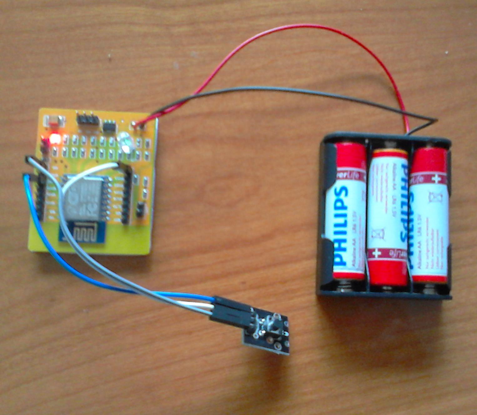
On another day every next week I will post IRcodes of one remote control. There are some articles ‘missing ‘ about some of the ( 37in1 or other ) sensors with the Arduino and i like to post (each week one article?) about this also. Posting an article about the ESP8266 Wifi and/or ESP8266Basic (with a (37in1) sensor or a project) is also on my todo (and wish) list.


In this blog article the first part of the serie about Adobe Photoshop with tips how to slice a picture of a remote control using "Adobe Photoshop Elements 6". And yes, you also can use other versions or the GIMP.
With newer versions you can also automate some parts of this slicing process.
You can do the slicing first in layers and afterwards save each layer as a separate picture. As there are several articles about using layers for editing pictures (and perhaps better written than i can do) i am not going to explain the concept of using layers.
Some tips and trick of using the layers i am going to explain. I expect you already have picture (of a remote control) that you want to slice in different pictures opened in Photoshop and saved as Photoshop format.
Most times the picture will be in "the background" layer, and that is not what i want.
- Make in a new layer a copy of the picture and rename the layer to ORG (the original picture as backup)
- Make in a second new layer a copy of the picture and rename the layer to EDIT (the picture you are going to edit).
- Delete the background layer.
- Hide (with the "eye") the ORG layer
- Select the "EDIT" layer.
- Make a grid visible to get horizontal and vertical helplines (In the menu [View] [Grid] )
- We slice horizontal and vertical and most times we need to rotate the image to adjust the positions of the buttons from the remote control { menu [Image] [Rotate] [Custom...] enter the angle and select right or left }
- Do the rotation in one time; If the angle is not correct undo ( Control Z) and try a better value.
- Now you are at a nice point to save the Photoshop file so you can come back here if something goes wrong.
and I am on a point to explain the Photoshop command SHIFT CTRL J
- Make a selection of a part of the picture in the EDIT layer.
- Press SHIFT CTRL J
- With the command SHIFT CTRL J you cut the selected part and put it in a new layer !
Next week i am going to explain the naming convention of the files for my sliced pictures.

Wednesday, August 3, 2016

ESP8266Basic KY-001 18B20 temperature sensor


Testing the ESP8266 with 18B20 temperature sensor
 ( KY-001 from 37in1Sensor kit )

Hardware connection

  •   Pin S Signal  - GPIO2 ( onewire )
  •   Pin middel VCC +3V3
  •   Pin - Ground

ESP8266Basic (version 3)

TEMP({DEVICE ID}):
Will retrieve temperature sensor reading from certain 1 wire devices connected to pin 2.
Bla = temp({Device ID})

ESP8266 Forum info

In article on http://www.esp8266.com/viewtopic.php?f=40&t=10402&p=49157&hilit=temperature#p49157
i found :
temp( 0 )  First temperature device
temp( 1 )  Second temperature device

ESP8266Basic program 

for (first) 18B20

'  TestKY019.bas  - 2016 V0.1

timer 3000 , [NewVal]
wait

[NewVal]
cls
msg$ = "<head><meta http-equiv='refresh' content='3'></head><H1>Temperature sensor </H1>" &  time() & " Temperature = " &  temp( 0 )
wprint htmlvar( msg$ ) 
returngui
wait

end


Friday, July 8, 2016

ESP8266 Basic IR sensor

ESP8266 Basis can also read Infra Red sensor
The manual of version 3 ESP8266Basic contains a little error IR receiver part.

ir.recv.setup(pin)
set the pin used for the IR reception (IR receiver connected to the pin)
example:
ir.recv.init(5) ‘set the pin 5
Needs to be
ir.recv.setup(pin)
set the pin used for the IR reception (IR receiver connected to the pin)
example:
ir.recv.setup( 5 ) ‘set the pin 5

I used the demo program below to test a  "TL1838 VS1838B 1838 38Khz Universal IR Infrared Receiver"  ( Aliexpress : 100 pcs less than 7 euro / The 37in1 Arduino KY-022 sensor should also work fine.) on pin GPIO14:

'  IR receive demo  ESP Basic 3.0.Alpha 8 
' http://blog.jeronimus.net

ir.recv.setup( 14 )
wprint "<h1> Testing IR input</h1>"
irbranch [DoIR]
wait

[DoIR]
wprint "<BR>IR received : " & ir.recv.full( )
returngui

return

end

Sometimes i did get an additional signal code "ffffffff:NEC:0" but most times i receive usable codes.

Tuesday, December 1, 2015

Arduino_KY-035_Class_Bihor_magnetic_sensor

Arduino KY-035 Class Bihor magnetic sensor

This sensor gives an analog signal

Hardware

  • S          Arduino Pin A5
  • middle  +5V
  • -           GND

Function

Without magnet 523
With one simple (not extreme strong) magnet values observed between 388 and 613

More info


Monday, November 30, 2015

Arduino_KY-024_Linear_magnetic_Hall_sensors

Arduino_KY-024_Linear_magnetic_Hall_sensors


Hardware

  • D0 (Digital Signal) Arduino D3 Only needed for "Digital script"
  • + +5V
  • G GND
  • A0 (Analog Signal ) Arduino A0 Only needed for Analog script"

Digital

When the linear Hall sensor detects a magnetic signal Arduino LED (pin 13)  (and led on module) flashes Arduino.


Analog

Value depends on position of magnetic field
Without magnet 523, with magnet between 417 and 730


More info


https://tkkrlab.nl/wiki/Arduino_KY-024_Linear_magnetic_Hall_sensors


Sunday, November 29, 2015

Arduino_KY-003_Hall_magnetic_sensor_module

KY-003 37-1 Hall magnetic sensor module 

Hardware

  • Pin  S                 D10
  • Pin middle (5V) +5V
  • Pin -                   GND -


Function

When the Hall sensor detects a magnetic field, Arduino LED (and the led on the sensor module) lights up.

Saturday, November 28, 2015

Arduino_KY-025_Reed_module

Arduino KY-025 Reed module

My version of this module has
2 leds:   power led and sensor led
4 pins + , G A0 (analog out) and D0 (digital out)
one IC( comparator ) and some resistors an a variable resistor (potmeter)On the internet you can also find a digital output only version of KY-025.

Hardware

  • D0 (Digital Signal)                 Arduino D3 (Only needed for Digital )
  • + +5V
  • G GND
  • A0 (Analog Signal )        Arduino A0 (Only needed for Analog  )

Digital


Function (Digital)

If power connected to the module the power led is on.
When a magnet is close to the sensor also the sensor led on the module is on and the pin 13 led on the Arduino will go on also.

Analog

On The Net i could not easy find an example using the KY-025 A0 analog pin.
I cloned an existing analog sensor script and tried it.


Function (Analog)

The reed sensor can only be closed (with magnet) or open (without magnet)  !!
With magnet i get the value is 1,  without magnet  1023.  Perhap the value can be changed with the potentiometer. (I did not try this.)

More info


Friday, November 27, 2015

Arduino_KY-021_Mini_magnetic_reed_modules

Arduino KY-021 Mini_magnetic reed module

A resistor is included on my version of this module.
For the test you need to keep a magnet ( not included in the 37in1 kit ) near the sensor.

Hardware

S         (signal) Arduino Pin 3
middle             +5V
-                      GND


Function

The reed contact is closes with a magnet near the sensor and the built in led on the Arduino is turned off (Pin 13)  Without magnet the led is on.

More info


Thursday, November 26, 2015

Arduino_KY-029_Yin_Yi_2-color_LED_module_3MM

Arduino KY-029 Yin Yi_2-color LED module 3MM

Same as KY-011 only different led size
Additional needed 330 Ohm resistor ( 2x)
On my version only the red led functioned the other was defective !

Hardware

  • Arduino pin 10 --> resistor 330 Ohm --> Signal pin of the module   (Green)
  • Arduino pin 11 --> resistor 330 Ohm --> Middel pin of the module  (Red)
  • Arduino GND  --> module -/GND
The circuit perhaps can work without the 330 Ohm resistor, however it is strongly recommended to add the resistors!


More info


Tuesday, November 24, 2015

Arduino_KY-020_Tilt_switch_module

Arduino KY-020 Tilt switch module

Arduino Ball switch module KY020
My version of this module has a debounce resistor.

Hardware

  • S          Arduino Pin 3
  • middle  +5V
  • -           GND


More info


Monday, November 23, 2015

Arduino_KY-036_Metal_touch_sensor_module

Arduino KY-036 Metal touch sensor module


Module has a power led and a led indicating touch of metal.
A0 seems to contain some analog out signal also to indicate if metal is touched.
Module contains a variable resistor (sensitivity?)

Connect

  • D0          Arduino Pin 3
  • +            +5V
  • GND       GND
  • A0          (not connected / Analog signal) 

Function

If metal wire over the transistor is touched Arduino led (pin13) is switched on

More info