

 For easy experimenting added resistors and a Dupont connector to a 'normal through hole' RGB led. Transparent heat shrink was added for electrical insulation and to keep the resistors (and the common pin wire) visible.
Wednesday, July 24, 2019
RGB led for experiments
For easy experimenting added resistors and a Dupont connector to a 'normal through hole' RGB led. Transparent heat shrink was added for electrical insulation and to keep the resistors (and the common pin wire) visible.
Friday, July 19, 2019
iTag Bluetooth tracker
 |
| iTag |
I ordered 5 of this iTags to see if they can really help me and my family to find items or prevent losing them. On the Aliexpress page i found 4 different colors so i received two of the same color.
The iTags came in a plastic bag with a small instruction on paper with QR code links to the software without the CR2032 Lithium (3V) battery. From the 5 iTags i received one did not work.
The cover of the battery compartment needs to be removed to put in the new battery. It is not mentioned in the manual but you can easy swap two covers with different colors. This way you can easy identify more than 4 distinct iTags without writing on it. You can make combinations like a Black iTag with a White battery cover.
 |
| iTag with battery cover of iTag of another color |
Keeping the push button on the iTag pressed 3 seconds sends outs two beeps on the iTag, a led on the iTag starts flashing and the iTag is switched on and can be connected to your phone using the app.
If the distance between the iTag an the phone is to big (and the Bluetooth signal gets weaker) an alarm can go off. In the app the distance can be set to short, medium and long. Also the distance unit can be switched between meters and foot. Depending on the settings the button on the iTag can also be used to activate an alarm on the Bluetooth connected phone, switch on voice recording, take a photo or store the current location.
It also should store current the location if connection between the tag and the phone is lost. To find lost items with the iTag and the app, or use the app for preventing loss of your items will be very challenging. The Bluetooth on the iTag can switch of after a few minutes. The connection will be lost and a false alarm will be triggered. Also finding your iTag back after leaving it somewhere a few hours will be quite impossible as the iTag will be switched off and not sending a traceable Bluetooth signal.
To use an iTag to find your phone also does not work as the connection between the iTag an the phone is not (always) restored automatic if it was disconnected and the Bluetooth signal is received again by the phone. Perhaps other apps (or another phone setting) will help to overcome this problem.
Also i noticed some small differences between similar looking iTags. I have seen photo's and video's where you can only see two battery connections and a white plastic when opening the battery compartment. In my iTags can see the PCB with some connections.
Besides the color there are also some other small visual differences between the iTags i got from my seller. Some have a small battery connections at the side and others have a somewhat bigger connection at the side to the +pole of the battery.
I don't know if there are other differences (e.g. in the internal hardware or software) of iTags that look similar.
Conclusion
The iTag i received switches off automatic and triggers false lost signals. Also one of the 5 cheap iTags was dead on arrival. Perhaps there are better iTags but due to this issue i can not recommend this iTag and i doubt if it can really help you find lost items.
More info
JG iTag Alarmhttps://www.youtube.com/watch?v=DvG5ymq46WI
The £1 Bluetooth Tracker https://www.youtube.com/watch?v=oYX8YKw3vGM
Tuesday, July 16, 2019
SMD project
 To get more experience with SMD soldering i build this led chaser.
The circuit of this running light consists of a 555 timer to make pulses
and a 4017 counter. Both ICs are SMD and also the two condensators C1 and C2 and the other 12 resistors.
The photo below shows the difference is size of a "standard" resistor and an SMD resistor.here are also small SMD leds, however "standard" red led lights are used.
To my surprise the SMD intergrated circuits where more easy to solder than the resistors and condensators.
I used a soldering iron, flux pen, tweezers and a magnifier glass.

Thursday, March 29, 2018
RFID and Wemos D1 mini (1)
I wanted to connect an RFID reader to my home network.
Therefore i used a ESP8266, more specific the Wemos D1 mini Wifi module.
As a test i created the circuit as a test on a breadboard using the Wemos D1 mini pin info on https://escapequotes.net/esp8266-wemos-d1-mini-pins-and-diagram/. (See also this picture with Wemos D1 mini connections)

The instructional also contains software to read basic RFID info and send it over the serial (usb) line.
https://github.com/Jorgen-VikingGod/ESP8266-MFRC522
THis did work and i expected that was a good starting point for the rest of my project.
Therefore i used a ESP8266, more specific the Wemos D1 mini Wifi module.
Test 1 (fail)
I found a project on http://www.instructables.com/id/WiFi-RFID-Reader/ using a Wemos D1 mini. The exact info about the pins was missing.| RFID | ESP8266 | Wemos D1 mini |
| RST | GPIO05 (free GPIO) | D1 |
| SS | GPIO4 (free GPIO) | D2 |
| MOSI | GPIO13 (HW SPI) | D7 |
| MISO | GPIO12 (HW SPI) | D6 |
| SCK | GPIO14 (HW SPI) | D5 |
| GND | GND | G |
| 3.3V | 3.3V | 3V3 |
define RFID module
#include "MFRC522.h"
#define RST_PIN 15 // RST-PIN for RC522 - RFID - SPI - Modul GPIO15
#define SS_PIN  2  // SDA-PIN for RC522 - RFID - SPI - Modul GPIO2
MFRC522 mfrc522(SS_PIN, RST_PIN);   // Create MFRC522 instance
Initialize RFID module
void setup() {
  Serial.begin(9600);    // Initialize serial communications
  SPI.begin();           // Init SPI bus
  mfrc522.PCD_Init();    // Init MFRC522
}
Read RFID tag
void loop() {
  // Look for new cards
  if ( ! mfrc522.PICC_IsNewCardPresent()) {
    delay(50);
    return;
  }
  // Select one of the cards
  if ( ! mfrc522.PICC_ReadCardSerial()) {
    delay(50);
    return;
  }
  // Show some details of the PICC (that is: the tag/card)
  Serial.print(F("Card UID:"));
  dump_byte_array(mfrc522.uid.uidByte, mfrc522.uid.size);
  Serial.println();
}

// Helper routine to dump a byte array as hex values to Serial
void dump_byte_array(byte *buffer, byte bufferSize) {
  for (byte i = 0; i < bufferSize; i++) {
    Serial.print(buffer[i] < 0x10 ? " 0" : " ");
    Serial.print(buffer[i], HEX);
  }
}
Unfortunate the example above did not working for me. I got output on the terminal, however there was a message about perhaps bad connections.Test 2 (succes)
More succesfull was the next example that i found this on github:https://github.com/Jorgen-VikingGod/ESP8266-MFRC522
Wiring RFID RC522 module
The following table shows the typical pin layout used:
| Signal | MFRC522 | WeMos D1 mini | NodeMcu | Generic |
|---|---|---|---|---|
| RST/Reset | RST | D3 [1] | D3 [1] | GPIO-0 [1] |
| SPI SS | SDA [3] | D8 [2] | D8 [2] | GPIO-15 [2] |
| SPI MOSI | MOSI | D7 | D7 | GPIO-13 |
| SPI MISO | MISO | D6 | D6 | GPIO-12 |
| SPI SCK | SCK | D5 | D5 | GPIO-14 |
- [1] (1, 2) Configurable, typically defined as RST_PIN in sketch/program.
- [2] (1, 2) Configurable, typically defined as SS_PIN in sketch/program.
- [3] The SDA pin might be labeled SS on some/older MFRC522 boards (including the one i used)
Define RFID module
#include "MFRC522.h"
#define RST_PIN 5 // RST-PIN for RC522 - RFID - SPI - Modul GPIO5
#define SS_PIN 4 // SDA-PIN for RC522 - RFID - SPI - Modul GPIO4
MFRC522 mfrc522(SS_PIN, RST_PIN); // Create MFRC522 instance
Initialize RFID module
void setup() {
  Serial.begin(115200);    // Initialize serial communications
  SPI.begin();          // Init SPI bus
  mfrc522.PCD_Init();    // Init MFRC522
}
Read RFID tags
void loop() {
  // Look for new cards
  if ( ! mfrc522.PICC_IsNewCardPresent()) {
    delay(50);
    return;
  }
  // Select one of the cards
  if ( ! mfrc522.PICC_ReadCardSerial()) {
    delay(50);
    return;
  }
  // Show some details of the PICC (that is: the tag/card)
  Serial.print(F("Card UID:"));
  dump_byte_array(mfrc522.uid.uidByte, mfrc522.uid.size);
  Serial.println();
}

// Helper routine to dump a byte array as hex values to Serial
void dump_byte_array(byte *buffer, byte bufferSize) {
  for (byte i = 0; i < bufferSize; i++) {
    Serial.print(buffer[i] < 0x10 ? " 0" : " ");
    Serial.print(buffer[i], HEX);
  }
}
Saturday, March 17, 2018
Voice Control V3 (2) Software intro
Due to some other activities it has been a while ago that i made my last post. This post is an introduction to the software for the Voice Control V3 Module.
The Voice Control V3 module is a relative cheap module that can recognize 80 words/phrases. However it only can recognize 7 words/phrases at the same time. To recognize sound you first need to train the words/phrases in a training mode. In the recognition mode you can load the phrase identification numbers in special registers. ( I now will use the word phrase in this post but it can also be s word or another sound).
 After this the module waits until the trained phrase is recognized and sends a signal.
I used the state machine idea in he software..
Each state has an id, the state id. When the system starts it starts in state one.
When a (new) voice recognition state is entered the 7 phrase id's are loaded in the module and the software waits until one of the 7 phrases is recognized..
When a phrase is recognized two things need to happen:
- An action is performed
- The machine enters a new state. (In this new voice recognition state the seven new (other) phrases are loaded, the module starts listening to [other] phrases until the module comes again in a new state.)
Each state also has a timeout. When no matching phrase has been recognized before a certain time this also triggers entering a new state and action to be performed.
State table for state(n)
When the actions are programmed the system can be configured loading a data table containing info about the PhraseId's, ActionId's, StateId's for each state like the state table above.
To make the software more robust i want to do the actions at the beginning of the new state after setting the timer for the timeout not at the end. Therefore after receiving the input trigger i immediate change state and pass the ActionId of the action that needs to be executed to the new state.
Steps after entering a new state are:
1) Set the timer for TimeOut.
2) Load new PhraseId's in the voice module.
3) Do the action (that need to be done due to the previous state change).
4) Wait for the new input triggers.
Other special actions that could be added are learning actions to learn a new voice command or a IR control code.
The Voice Control V3 module is a relative cheap module that can recognize 80 words/phrases. However it only can recognize 7 words/phrases at the same time. To recognize sound you first need to train the words/phrases in a training mode. In the recognition mode you can load the phrase identification numbers in special registers. ( I now will use the word phrase in this post but it can also be s word or another sound).
 After this the module waits until the trained phrase is recognized and sends a signal.
I used the state machine idea in he software..
Each state has an id, the state id. When the system starts it starts in state one.
When a (new) voice recognition state is entered the 7 phrase id's are loaded in the module and the software waits until one of the 7 phrases is recognized..
When a phrase is recognized two things need to happen:
- An action is performed
- The machine enters a new state. (In this new voice recognition state the seven new (other) phrases are loaded, the module starts listening to [other] phrases until the module comes again in a new state.)
Each state also has a timeout. When no matching phrase has been recognized before a certain time this also triggers entering a new state and action to be performed.
State table for state(n)
| State | Input | Load | Output | Output |
|---|---|---|---|---|
| StateN | 1 | PhraseId | ActionId | NewStateId |
| StateN | 2 | PhraseId | ActionId | NewStateId |
| StateN | 3 | PhraseId | ActionId | NewStateId |
| StateN | 4 | PhraseId | ActionId | NewStateId |
| StateN | 5 | PhraseId | ActionId | NewStateId |
| StateN | 6 | PhraseId | ActionId | NewStateId |
| StateN | 7 | PhraseId | ActionId | NewStateId |
| StateN | TimeOut | TIME | ActionId | NewStateId |
When the actions are programmed the system can be configured loading a data table containing info about the PhraseId's, ActionId's, StateId's for each state like the state table above.
To make the software more robust i want to do the actions at the beginning of the new state after setting the timer for the timeout not at the end. Therefore after receiving the input trigger i immediate change state and pass the ActionId of the action that needs to be executed to the new state.
Steps after entering a new state are:
1) Set the timer for TimeOut.
2) Load new PhraseId's in the voice module.
3) Do the action (that need to be done due to the previous state change).
4) Wait for the new input triggers.
The details can be loaded from a table and some variables like the Previous_ActionId.
TimeOut also protects for timeout of the actions as it is set before the execution of the action. If needed an action can modify or stop and later restart the watchdog timer to give it more time to execute.
TimeOut also protects for timeout of the actions as it is set before the execution of the action. If needed an action can modify or stop and later restart the watchdog timer to give it more time to execute.
Changing a state can only trigger one action. To facilitate execution of multiple actions after receiving a trigger special states are added: A (numerical) range of states do not load PhraseId's and wait for voice command. This states only execute the actions. When the action is ended it immediately enters a new state.
Special states are also:
0 stop No actions are executed. The system stops.
1 boot No actions are executed. All variables are reset This is the first state that will be executed when system powers up.
Besides the voice input and timeout other triggers can be used to change the state. The module can have hardware like (one one multiple) push buttons or an IRreceiver.
Actions that can be performed also depend on the other hardware. The most simple action is a dummy action that does nothing. Other actions can be e.g. a led (color or blinking), a buzzer to give visual or audio feedback. An IR-transmitter can sends out a IR remote control code, a 433MHz transmitter or bluetooth transmitter for a radio control signal or if connected to an network e.g. a http://request.Other special actions that could be added are learning actions to learn a new voice command or a IR control code.
However the best is not to make your voice recognizer to complex. Let your home automation system control of your home hardware. Let the voice recognizer module communicate to your home automation system. (and only add a led and a buzzer for some feedback.)
To connect the Voice Recognizer V3 to your home automation system using Wifi is a (simple and cheap) ESP8266 module (e.g. the Wemos D1 mini) can be used. This will be presented in one of the next posts about this topic.Wednesday, August 2, 2017
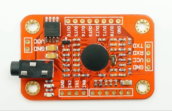
Voice control V3 (Part 1)
An interesting input device is the ElecHouse Voice Recognition Module V3. It comes with a microphone and some pins to solder on the PCB. I ordered my "1set Speed Recognition, Voice Recognition Module V3" module on Aliexpress (between 17 and 18 euro 2017).
The question is what can this module do for your projects and how can you use it? The answer is simple: it can recognize your voice and output a signal depending on the word or short phrase that you have learned the module. The good news is that (according to the spec) you can train this relative cheap module to recognize 80 words or phrases. These words or phrases are stored in memory on the module. The bad news is the module can only recognize 7 different phrases at the same time. And you also need to train the system first with all your phrases.
You can create a system that knows what to do with commands like:
"James light on"
"James light off"
"James light color white"
"James light color green"
"James light color blue"
"James light color yellow"
"James light dim 25"
"James light dim 50"
"James light dim 75"
"James light dim 100"
"James TV off"
"James TV on"
"James TV channel next"
"James TV channel prev"
"James TV channel one"
"James Radio on"
"James Radio off"
And yes, this are much more than 7 phrases! You can do this using a menu structure!
 Teach the system all the separate words ("James", "light", "TV" ," Radio" "color" etc.)
Load only the word "James". If the module recognizes "James" load the three words "light" "TV" Radio" if the module recognizes "light", load the words "on" "off" "color" "dim" and build a menu system.
You can get the same (or even better) effect with Amazon Alexa or a Google app on your android. Using this module the voice recognition finds happens inside the module. You do not need internet access and perhaps even more important the privacy: The audio is not transmitted to the internet.
A small disadvantage is that you need to train the module. My first test of the module was with an Ardhuino Uno. The ElecHouse website has a link Arduino library with some examples including a voice training example. Connect GND and VCC (5v) , RXD to Arduino pin 3 and TXD to Arduino pin 2. (If you do not like to use pin 2 and 3 you can use other pins. However you need to make a small change in the software). You only need to connect this four pins on the V3 module (and the included microphone) to a working Arduino to start.
Some info from ElecHouse about the module:
ELECHOUSE Voice Recognition Module is a compact and easy-control speaking recognition board.
This product is a speaker-dependent voice recognition module. It supports up to 80 voice commands in all. Max 7 voice commands could work at the same time. Any sound could be trained as command. Users need to train the module first before let it recognizing any voice command.
This board has 2 controlling ways: Serial Port (full function), General Input Pins (part of function). General Output Pins on the board could generate several kinds of waves while corresponding voice command was recognized.
What's new?
We already have Voice Recognition module V2. It supports 15 commands in all and only 5 commands at the same time.
On V2, voice commands are separated into 3 groups while you training it. And only one group (5 commands) could to be imported into Recognizer. It means only 5 voice commands are effective at the same time.
On V3, voice commands are stored in one large group like a library. Any 7 voice commands in the library could be imported into recognizer. It means 7 commands are effective at the same time.
Parameter
Voltage: 4.5-5.5V
Current: <40mA
Digital Interface: 5V TTL level for UART interface and GPIO
Analog Interface: 3.5mm mono-channel microphone connector + microphone pin interface
Size: 31mm x 50mm
Recognition accuracy: 99% (under ideal environment)
Feature
Support maximum 80 voice commands, with each voice 1500ms (one or two words speaking)
Maximum 7 voice commands effective at same time
library is supplied
Easy Control: UART/GPIO
On internet is a lot more info about this and similar modules. Here is link to a YouTube video : S134 - Voice Recognition Module V3
 |
| Voice Recognizer V3 & Arduino Uno |
You can create a system that knows what to do with commands like:
"James light on"
"James light off"
"James light color white"
"James light color green"
"James light color blue"
"James light color yellow"
"James light dim 25"
"James light dim 50"
"James light dim 75"
"James light dim 100"
"James TV off"
"James TV on"
"James TV channel next"
"James TV channel prev"
"James TV channel one"
"James Radio on"
"James Radio off"
And yes, this are much more than 7 phrases! You can do this using a menu structure!
 Teach the system all the separate words ("James", "light", "TV" ," Radio" "color" etc.)
Load only the word "James". If the module recognizes "James" load the three words "light" "TV" Radio" if the module recognizes "light", load the words "on" "off" "color" "dim" and build a menu system.
You can get the same (or even better) effect with Amazon Alexa or a Google app on your android. Using this module the voice recognition finds happens inside the module. You do not need internet access and perhaps even more important the privacy: The audio is not transmitted to the internet.
A small disadvantage is that you need to train the module. My first test of the module was with an Ardhuino Uno. The ElecHouse website has a link Arduino library with some examples including a voice training example. Connect GND and VCC (5v) , RXD to Arduino pin 3 and TXD to Arduino pin 2. (If you do not like to use pin 2 and 3 you can use other pins. However you need to make a small change in the software). You only need to connect this four pins on the V3 module (and the included microphone) to a working Arduino to start.
Some info from ElecHouse about the module:
ELECHOUSE Voice Recognition Module is a compact and easy-control speaking recognition board.
This product is a speaker-dependent voice recognition module. It supports up to 80 voice commands in all. Max 7 voice commands could work at the same time. Any sound could be trained as command. Users need to train the module first before let it recognizing any voice command.
This board has 2 controlling ways: Serial Port (full function), General Input Pins (part of function). General Output Pins on the board could generate several kinds of waves while corresponding voice command was recognized.
What's new?
We already have Voice Recognition module V2. It supports 15 commands in all and only 5 commands at the same time.
On V2, voice commands are separated into 3 groups while you training it. And only one group (5 commands) could to be imported into Recognizer. It means only 5 voice commands are effective at the same time.
On V3, voice commands are stored in one large group like a library. Any 7 voice commands in the library could be imported into recognizer. It means 7 commands are effective at the same time.
Parameter
Voltage: 4.5-5.5V
Current: <40mA
Digital Interface: 5V TTL level for UART interface and GPIO
Analog Interface: 3.5mm mono-channel microphone connector + microphone pin interface
Size: 31mm x 50mm
Recognition accuracy: 99% (under ideal environment)
Feature
Support maximum 80 voice commands, with each voice 1500ms (one or two words speaking)
Maximum 7 voice commands effective at same time
library is supplied
Easy Control: UART/GPIO
On internet is a lot more info about this and similar modules. Here is link to a YouTube video : S134 - Voice Recognition Module V3
Tuesday, July 18, 2017
Solar charger teardown
 Several YouTube video review channels do sometimes a product teardown. When i ordered two of this Aliexpress i had no plans to do a teardown.
solar chargers at
When i orderd the power banks in february 2017 the Pcs 8000 mah Portable Solar Power Bank waterproof Enternal battery power bank phone charger for Iphone HTC Lenovo Mipad did cost € 6,51 each and i wanted to test them to use them for IOT devices, perhaps outdoor. and low power.

Features (according to seller):
8000mAh solar charger external battery power bank
Build-in 8000mAh lithium polymer battery
Super waterproof and dustproof.
Strong shockproof and drop resistance.
With dual USB and micro USB ports.
Emergency LED torch, the LED flashlight works perfectly in darkness, especially for emergency.
4 LED status of charge indicators indicate the charging and discharging process
Environmentally friendly silica gel and ABS+PC materials, and rubber paint surface process
 Compact, portable & stylish design.
Specifications:
Model:S69
Battery Capacity: 8000mAh Li-polymer battery
Solar panel: 5V, 200mA
Power: 4W
Input: DC 5V/ 1A
 Output: DC 5V/ 2 x 1A
Product size: 142* 75*13.6mm
Operation Temperature: 0-45 degree
Weight:140 g
Compatible: for iPhone, iPad, Android phone, GPS device, camera (most devices that use a USB cable to charge).
Color: ... (several colors available)
The package included:
1 x Solar Charger
1 x Free carabiner
1 x Micro USB charging cable
Super waterproof and dustproof, strong shockproof and drop resistance. That would be nice for an outdoor IOT application.
( Now in july the seller only has e.g. Vidar waterproof 5000mah solar power bank polymer-Li portable solar charger. I can not find "my" 8000 mah version for a comparable price (yes i found some other 8000 mah power banks.)
One of the solar devices was put in my car under the window. I almost did forget it and now a semi automatic teardown has happened. Due to the heat of the sun one the power banks has opened itself.
 |
| Warning on the package!! |
In a car behind the window the temperature can rise quick. In the specs/description an operation temperature of 0-45 degrees is mentioned.
I posted this as a warning do not let the powerbank in your car behind the glass and to show pictures of the solar powerbank and the batteries after further opening it. One of the batteries has changed of shape and the enclosure can not be closed anymore.

I did not a complete teardown as i wanted to rescue parts and the enclose. (And perhaps build an IOT device inside it). To look inside i opened it a bit more. You can see the solar cell, a PCB and two (different) battery packs in parallel. According to the specs these two packs can deliver together the 8000 mah.


Monday, July 17, 2017
Microwave Radar Sensor RCWL-0516 with Arduino Uno

At Aliexpress i found 5 pieces for € 2,19 => € 0,44 / piece.
Info how to wire the device and a test program was found on https://www.14core.com/wiring-the-rcwl0516-auto-induction-doppler-microwave-radar-with-esp826632arduino/
I soldered some wires with Dupont connectors to one of my RCWL-0516 modules and tested the program with an Arduino Uno (clone). Not yet with ESP8266, perhaps that will come in another RCWL-0516 post. It found some little errors that i needed to corrected. When changing the program i also did put the serial output on one line for each change with a millis() timestamp.

The program after my changes:
/* 14CORE | DOPPLER RADAR TEST CODE
*************************************
From https://www.14core.com/wiring-the-rcwl0516-auto-induction-doppler-microwave-radar-with-esp826632arduino/
Modified
2017 July 17 by @JanJeronimus / Correction 'bool sens;'& 115200 / Output one line , added additional and spacesMillis()
*/
static bool value = -1;
bool sense;
const int8_t Output = 13;
#ifdef ESP8266
const int8_t sensor = D2;
#else
const int8_t sensor = 2;
#endif
void setup(){
Serial.begin(115200);
#ifdef ESP8266
Serial.println(" 14CORE | DOPPLER RADAR TEST CODE");
Serial.println("==================================");
Serial.println("ESP8266 Started......");
digitalWrite(Output,1);
#else
Serial.println("Arduino MCU Started......");
digitalWrite(Output,0);
#endif
pinMode(Output, OUTPUT);
pinMode(sensor, INPUT);
}
void loop(){
sense = digitalRead(sensor);
if (sense != value){
Serial.print( millis());
Serial.print(" Raw Value : ");
Serial.print(sensor);
Serial.println(sense ? " +HIGH" : " -LOW");
#ifdef ESP8266
digitalWrite(Output, ! sense);
#else
digitalWrite(Output, sense);
#endif
value = sense;
}
delay(20);
}
To use the program you need to connect 3 pins
GND
OUT - connect this to an input pin (Arduino D2)
VIN 4 to 28 volt
It seems the CDS pin can be used to disable detection. You need not to connect it.
The 3V3 pin is for output not input! (Interesting to try if it can be used to power an ESP8266!)
The sensor works fine and can detect motion even behind obstacles. It can detect motion at about 3 to 4 meter distance.

Some other references
Two videos about the RCWL-0516 by nenioc187 :Specs & Pin info :
https://www.elecrow.com/rcwl-0516-microwave-radar-sensor-switch-module-body-induction-module-4-28v-100ma.html
https://github.com/jdesbonnet/RCWL-0516/
Subscribe to:
Posts (Atom)


