

I could make some time to build my Geiger counter to measure radioactivity.
For some time i had a kit laying around to build a Geiger counter. The counter can also be interfaced to an Arduino , ESP32 or other system. Standard it has an led and a buzzer to give the typical tick sounds of a Geiger counter. On the PCB are the component numbers.

All different components are in separated parts of a plastic foil with a B(uild) O(f) M(aterials) list as index.
There was no real guidance for building, however on the BOM is a link to a github page https://github.com/2969773606 .
I started with the resistors and after that the capacitors followed by other components. A bit a mix of less fragile to more fragile components and low to higher components compartment by compartment. Each time marking when everything was soldered. For certainty i also tested most of the components before soldering.
A strange thing is that on the PCB is a component that is not in the box. As i did not see this component soldered on any picture or video about this Geiger counter i expect it was not needed. In the picture of the PCB with components (below) you can see the open position above the radiation symbol.

Also to find the purpose of the potmeter and jumpers you need to look in details on the github page.
The potmeter is used to control the voltage for the Geiger tube. According to this document on github https://github.com/2969773606/GeigerCounter-V1.1/blob/master/En_Calibration_GMv1.1.pdf it is precalibrated and i did not change it (yet).
In the schematic https://github.com/2969773606/GeigerCounter-V1.1/blob/master/Sch__Geiger%20Counter%20Kit-v1.1.pdf you find the jumpers.
J1 is to disconnect the speaker (buzzer) . I did not yet play with it,


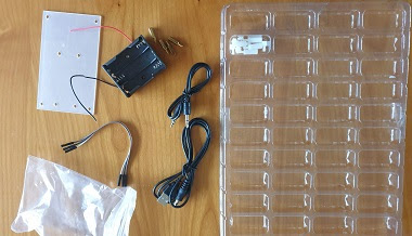
In the Geiger counter kit is a battery holder, and audio connector cable, a 5V USB cable, a plastic shield, some metal and plastic stands.
When i finished building and checked the PCB i powered it up using the USB cable in a USB power supply and i did hear some random radioactivity ticks. This is the standard background radiation and also some background noise from the tube. And yes it works with the open position for a component above the radiation symbol.
As for the Geiger Tube high voltages are used i switched off the system and added the protection shield using the plastic stands. (I don't like the metal stands for this). I also want to add some protection to the bottom (perhaps using some plywood using more plastic stands as i expect the high voltages will also be at the bottom of the PCB.
I don't know yet when i will write and post Geiger counter -2- . Perhaps after some experiments with interfacing this counter to an Arduino or ESP and measuring some radiation.


No comments:
Post a Comment