Showing posts with label breadboard. Show all posts

Monday, January 30, 2023

ESP32_BreadboardFriend

PCBs to make ESP32 more breadboard friendly Including jumpers to select ground and power connections. 

To fit my ESP32 module nice on a breadboard i created this PCB.  When you stick this EPS32 module direct on a PCB there is no space to make connections. You can find several examples where users stick the module  on two PCBs. However wanted to keep the 'standard' PCB height and put it on only one breadboard. Therefore i created this PCB for my EPS32 module that can be plugged in the power lines of a breadboard.
To connect to the power rails of a breadboard solder some male pins pointing downwards in the top left, bottom left , top right and bottom right holes.

For the jumper connections it is best to solder in male Dupont pins. 

I soldered female Dupont connectors in the corresponding holes in the PCB for the module and the connections.
For the connections it is also possible to use male Dupont headers (or a combination of male and female). However the female version as it gives it a breadboard look. (I also build a version with 2 female one male row connection row. This is handy if you have sensors and buttons with female connectors.)


In the photo you see a version where i used male pins for some additional connections (GND,  3V3 and 5V) 

The PCB can also be used as 'stand alone' without a breadboard.  Mount the PCB using screws in the holes, the ESP module can easy be swapped or temporary removed for testing and reprogramming. 

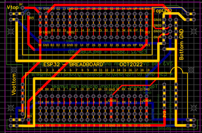
Using jumpers power and ground connections can be configured.
(For the two power strips top row is always + bottom -)
The yellow lines indicate the connections.
Topright part of the PCB is the Ground configuration. The jumpers make it possible to connect GND1 GND2 GND3 GND4 to the top ground or to the bottom ground line.
Also bottom ground and top ground can be connected to each other.
On right bottom part of the PCB you find (vertical) some 3V3 points and Bottom ground connection points.
On left bottom part of the PCB you find (vertical) some 5V connection points.
Also on the left (bottom and top) there are 5V ans 3V3 points that can be connected to the breadboard top or bottom + power line.

The left and right power lines are always connected. You can use the PCB also to join to breadboards placed left and the right.

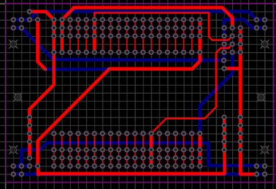
Below some pictures of the PCB design. 
( Red top copper layer, Blue bottom copper layer)


The PCBs where designed with EasyEDA and the project is there also shared.
Project homepage https://oshwlab.com/jeronimus.net/esp32breadboard_copy

Open in Editor
https://easyeda.com/editor#cmd=new_schematic,cmd_for_project=a2568d38d6634a1185e5220d4f53b901
PCB Top layer

PCB Bottom layer

The information, including the gerber files is also available on my Github
https://github.com/JanJeronimus/ESP32_BreadboardFriend 

Friday, January 6, 2023

How to get a Raspberry Pi 4 for free.

How to get a Raspberry Pi 4 for free in The Netherlands.
 I received a new Raspberry Pi 4 with help of the Dutch Government. Due to the chip shortage is is difficult to buy a new Raspberry Pi and also the prices age gone up a lot.
However i just received Raspberry Pi 4 sponsored by the Dutch Government. This together with a book, a breadboard and some components. And perhaps you can also get this. How is that possible?
{IMG of the Pi}

For many years in the Dutch Tax system you could get a tax deduction if you followed a job related study or training and spent more than a certain amount. However the tax rules did change some time ago. Now, in the Netherlands, you can apply each year for 1000 Euro's for a job related training using a 'Stap budget'. However this is a limited government budget and only a few moments per year when you can apply and the training needs to be on an approved list. When the application time is there you already need to be in the waiting list as the budget is quite limited. Also you need to finish the training otherwise you need to pay it yourself.. 

What has this to do with a free Raspberry Pi ?  There are many interesting training's available also several IT related, including a Raspberry Pi Programming (using Python) . When you have finished your training you get a certificate of attending and you can (/must) do an exam. Included with the training is a Raspberry Pi, a breadboard and some components. As the training costs less than 1000 Euro's you can get this training for free with the Dutch Stap budget mentioned above. So you will not only have a Raspberry Pi a breadboard and some components. You can learn something and get an certificate and diploma.

Be aware that the apply process is quite difficult. I used the time slot at 1 November 2022 at 10:00. Before that you need to register first for the course and get some information from the company that provides the training. A long time before my time-slot i already went to the registration page for the Stap budget. There you end up in a queue. (You can also go there on second device or with another browser to double your chance. ). At 10:00 i got a message that i was in a waiting list that would take more than an hour. 

Also several times i got a message that the waiting list was paused.


I did not need to worry and would keep my place in the queue. Finally after more than an hour an a half i got a message that the queue was around 60 minutes. and after that every minute the queue became a minute shorter. At around 12:30 (so more than 2 and a half hours) i could register.


A strange thing is that about 10 minutes after i was in the queue i decided to also go a second time in the queue (as mentioned above).  I could register using this second queue. In the first queue i opened my turn would be more than 50 minutes later than in the second queue. So there is also a lot of luck involved.

Due to the long waiting time I did think my chances where very low. If you do not get the Stap budget you do not need to follow the training or pay anything. After some days i got a first email that my application for the Stap budget was approved and a few weeks later a mail from my training provider.
Some time later i received a package from the training provider with the Pi and training information.
Within a year i need to finish the training.

Wednesday, September 21, 2022

Audio transformer - breadboard friendly

Some time ago i ordered some cheap 600:600 ohm audio transformers to use them for some experiments. To easy wiring up an experiment it is possible to plug a transformer direct in a breadboard. The audio transformers fit exactly in a 3*4 grid on a breadboard. (With normal mains transformers I would not recommend this as i don't think it is safe to use high voltages or mains on a breadboard.)
I liked to make a more breadboard friendly version to handle the little transformer more easy, make it easy to move the transformer to other places on the breadboard and have the connections always at the same distances and also get somewhat more robust pins.

 A special PCB for the transformer could have been created, however i still had some 8 pin SMD PCBs and i realized they can be easy adapted for this transformers. This are small PCBs, normally used for 8 pin SMD ICs to making through hole compatible (or make them usable on a breadboard).

At the copper connections for the 8 pin SMD IC some connections were made:  pin 1 to 2 , 3 to 4 , 5 to 6 and 7 to 8. A small wire with some solder to bridge the gaps was used as solder alone tended to flow back on the pads. When you want a connection it sometimes does not work and when you don't want a connection.... 
The wires of the audio transformer fit exactly as 3*4 grid in pin holes 2, 4, 5, and 7. However first the Dupont male pins at pin 1, 8, 3 and 6 (see photos) were soldered as soldering the transformer first would make it more difficult.
For stability 2 strips with 4 male Dupont pins were used, first removing the middle 2 pins as they are not needed.  
1234


8765
The green positions are wires for the audio transformer and at the red positions are for the Dupont pins.  As there are connections between pin 1-2 , 3-4 , 5-6 and 7-8 the transformer is now breadboard friendly.
(Picture with breadboard, a breadboard friendly and a direct plugged in audio transformer and some other components)

Sunday, December 15, 2019

SMD Leds breadboard friendly -2-

Mailbag
August 2019 i published how to make SMD leds breadboard friendly with Dupont connectors.  https://blog.jeronimus.net/2019/08/smd-led-breadboard-friendly.html

Another option to make SMD components more breadboard friendly is to using a PCB. I found some SMD PCBs on Aliexpress and ordered 3 lots with 10 PCBs. (30 PCBs in total)
The PCBs arrived some days later in my mail in a small envelope. See "Mailbag" picture on the right. They match DIP 8 format and you need to break them apart yourself.
Besides for DIP 8 IC's these PCBs can also be used for other SMD components.
For a test I soldered some different SMD leds on them. To solder the Dupont pins to the PCB i used a small breadboard to temporary fix the Dupont pins at the right positions.


Wednesday, August 14, 2019

SMD led breadboard friendly.

I wanted to do some easy prototyping with SMD leds (and other components).
SMD components are available in different (small) sizes.
One of the ways I made the SMD leds breadboard friendly is as follows:

1) Put an SMD led and a long Dupont pin connector on your workbench,
2) If the SMD led is somewhat bigger remove a pin (the second pin) from the connector.
3) Tin the Dupont connector where it needs to be connected to the led.
4) Push the Dupont connector on the led and solder by heating the connector. If needed add a little solder.
5) Cut the connector on the desired size (2 or '3' ) pin.
6) Test the led and the connections using a led tester.

By cutting the connector after soldering it is more easy to push the connector on the led and making the solder join.

On the picture you see at the left some end results and at the right a "standard" red led as size reference.
On the bottom left a " big" SMD led with a Dupont connector with the middle male pin removed.
The other 3 SMD leds are smaller leds that fit on two pins.