Saturday, February 29, 2020

Vampire_Teeth_Fangs

Found interesting cheap product on Aliexpress "Vampire Teeth Fangs"
A kind of white plastic/gel that easy can be given a shape in hot water.
It is sold to make temporary Vampire Teeth or other artificial false teeth. (So it should be non toxic as you can put it in your mouth.)
However it looks an interesting product to make other small plastic items. According to the description this gel can also be reused.
(There is no instruction how to clean it)

Instruction from the sellers website:
Feature:
  • 100% high quality.
  • Quantity: 15g
  • Size: about 4mm
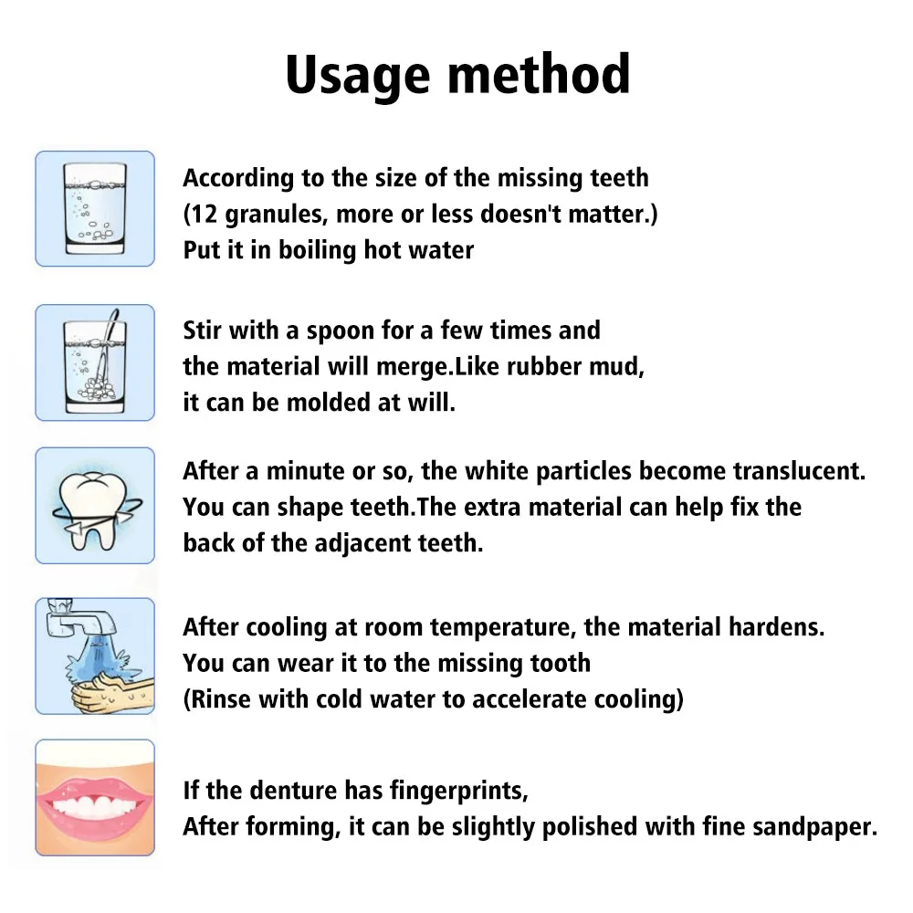
  • Using Instruction of Tooth Solid Gel
  • 1, Prepare a cup of boiling water and pour the amount of about 15 pieces of gel (for one piece of fangs)
  • 2, Stir in the cup and then get it out when it goes to be transparent
  • 3, Make the gel cooled for about 5 seconds after taking it out of the cup. And then put the gel in into the fangs’ slot so that you can glue the fangs to your own teeth, using your hands to squeeze the gel to both the gaps between teeth and the inner side of your teeth. This can make all of this to be a complete and compatible tooth socket.
  • 4, Get the tooth socket out and cool it for some minutes till the gel become white.
  • 5, Repeat these steps for another fangs. Please note that these teeth sockets can be used for several times.
  • Kindly Note: Please do not drink hot drinks when wearing the teeth sockets. Please be careful
  • when you are making the teeth sockets, do not be scalded!

Package content:

1x 15g Temporary Tooth Repair Kit Teeth And Gaps FalseTeeth Solid Glue(Not Including Fangs Dentures)

Q4 2019 i did buy it (together with some products from the same seller) for 1.20 € at https://www.aliexpress.com/item/33037962502.html?spm=a2g0s.9042311.0.0.28b14c4doKTSW1 (shipping from China). According to the sellers information it can be bought for about half the price in US. However it was not possible to ship it to where i live.
The volume/quantity was less than expected however sufficient to do some experiments creating small plastic objects.
As i do not have any reliable toxicity information i have some hesitations to use it for making false teeth and/or put it in a mouth. So any use like this will be at your own risk!

Friday, February 28, 2020

COVID-19 data -1-

With the current corona virus outbreak reliable data about occurrences is important.

In response to this ongoing public health emergency, the Johns Hopkins University, developed an interactive web-based dashboard (static snapshot shown above) hosted by the Center for Systems Science and Engineering (CSSE) at Johns Hopkins University, to visualize and track reported cases in real-time. The dashboard, first shared publicly on January 22, illustrates the location and number of confirmed COVID-19 cases, deaths and recoveries for all affected countries. It was developed to provide researchers, public health authorities and the general public with a user-friendly tool to track the outbreak as it unfolds. Further, all the data collected and displayed is made freely available, initially as google sheets, now in a GitHub repository, along with the feature layers of the dashboard, which are now included in the ESRI Living Atlas.
This is the data repository for the 2019 Novel Coronavirus Visual Dashboard operated by the Johns Hopkins University Center for Systems Science and Engineering (JHU CCSE). Also, Supported by ESRI Living Atlas Team and the Johns Hopkins University Applied Physics Lab (JHU APL).
The website and its contents herein, including all data, mapping, and analysis (“Website”), copyright 2020 Johns Hopkins University, all rights reserved, is provided to the public strictly for educational and academic research purposes. The Website relies upon publicly available data from multiple sources, that do not always agree. The Johns Hopkins University hereby disclaims any and all representations and warranties with respect to the Website, including accuracy, fitness for use, and merchantability. Reliance on the Website for medical guidance or use of the Website in commerce is strictly prohibited.

The data on github is available as .csv files. In this blog post i will explain how his data can be imported easy in a google spreadsheet. The data than can be used to create your own graphs or make special calculations.
In github you can view the *.csv data and the button [raw] opens a page with the raw csv file. Using the URL in the google spreadsheet function fills the spreadsheet with the github data.
 Currently there are 3 important time-series data files:

https://raw.githubusercontent.com/CSSEGISandData/COVID-19/master/csse_covid_19_data/csse_covid_19_time_series/time_series_19-covid-Confirmed.csv

https://raw.githubusercontent.com/CSSEGISandData/COVID-19/master/csse_covid_19_data/csse_covid_19_time_series/time_series_19-covid-Deaths.csv

https://raw.githubusercontent.com/CSSEGISandData/COVID-19/master/csse_covid_19_data/csse_covid_19_time_series/time_series_19-covid-Recovered.csv

A simple recipe to get this data in your own google spreadsheet:

Create a spreadsheet with 3 pages.
Rename these pages to Confirmed, Deaths and Recovered.
Place cel A1 of each of this pages the link to the corresponding raw data. (See above)
Put in each of this three pages in another cell (e.g. in A3  this formula:

=IMPORTDATA(A1)

Each time this function gets executed it will grab the data from github.
So when the github data gets updated new data will appear automatic in your spreadsheet and can be used to create custom graphs, do custom calculations or use a special script in your spreadsheet.
This also uses some bandwidth an gives addition load. If you want to present this data give credits to Johns Hopkins University, respect their use policy and for a high traffic website better do not use this data direct as shown in this example. Grab periodical fresh data and use a local copy (e.g. with wget command in a cronjob.)

(Update 10 March 2020 : I added -1- in the title and added the COVID-19 label as i decided to do another post about COVID-19 data  perhaps more posts will follow. )


(Important (27 March 2020) see also https://blog.jeronimus.net/2020/03/covid-19-data-3.html as files in Github changed! )

ATTiny Charlieplex 4 RGB leds

Experimented using 4 charlieplexed RGB leds on a attiny85.
This experiment was done some time ago, and due to the result (watch video below) i hesitated to post it as at that time it was not complete successful.  There are several excellent resource that explain charlieplexing. Therefor i will not try to explain it in detail. In short as leds only light up when the current flows in one direction you can control more leds to a circuit.
I used the code below.

CODE

void setup() {              
  // charlieplex 4 RGB leds 0 1 2 3
  // initialize the digital pin as an output.
}

// the loop routine runs over and over again forever:
void loop() {
 int mydelay = 1000;

  LEDon(3, 2);  // 1R
  delay(mydelay);
  LEDon(3, 0);  // 1G
  delay(mydelay);
  LEDon(3, 1);  // 1B
  delay(mydelay);

  LEDon(0, 1);  // 2R
  delay( mydelay );
  LEDon(0, 3);  // 2G
  delay( mydelay );
  LEDon(0, 2);  // 2B
  delay( mydelay );

  LEDon(1, 0);  // 3R
  delay(mydelay);
  LEDon(1, 2);  // 3G
  delay(mydelay);
  LEDon(1, 3);  // 3B
  delay(mydelay);

  LEDon(2, 3);  // 4R
  delay(mydelay);
  LEDon(2, 1);  // 4G
  delay(mydelay);
  LEDon(2, 0);  // 4B
  delay(mydelay);
}

void LEDon( int gnd, int vin) {
  pinMode(0, INPUT);
  pinMode(1, INPUT);
  pinMode(2, INPUT);
  pinMode(3, INPUT);
//  pinMode(4, INPUT);
//  pinMode(5, INPUT);

  pinMode(vin, OUTPUT);
  pinMode(gnd, OUTPUT);
  digitalWrite(vin, HIGH);
  digitalWrite(gnd, LOW);
}

ENDCODE

When you watch the video you seen some unwanted / unexpected flashes of an RGB led.
This is due to the fact that the attiny85 has an on-board led connected to one of the pins. This interferes with the charlieplexing. To remove this unwanted behavior of the RGB led you need to remove this led.
My first idea was to first make a recording of the correct behaving RGB leds before posting everything on my blog. I did not yet made a video recording after modifying an attiny85. However i later made a custom PCB for charlieplexing. I now decided to post it withe the error due to the led and make later a posting about that PCB where you can see the correct functioning of the RGB leds.


Thursday, February 6, 2020

FPGA first steps -1-

My last blog post was more than a month ago. However this does not mean that i did not projects or learned new things. For a long time i wanted to do something with FPGAs but never found a good way to start.
Recently i did some research how to start with board below 22 euro from AliExpress. I found some boards. e.g. the EP2C5T144 and EP4CE6E22C8N Altera FPGA Cyclone ii and iv development boards. These boards also need an USB blaster (that only a cost a few euros). They are not the newest boards but offer a cheap way to start.

Sooner than expected i received EP2C5T144 Altera Cyclone ii development board from China. This blog post is a short introduction also to log results of some of my experiments until now.
The Cylone ii is an older FPGA that is not supported anymore in the newest software only Quartus II version 13.1 (servicepack p1 version 13) or lower can be used. There is a free version of the software. Registration for download is required. The software can be a bit confusing as it has many options. The free version is sufficient to use the FPGA. Some options only work in the payed version.
There are warning not to use directory or file names with spaces.
The development board came together with an USB blaster. The 4 Dupont connectors 2*14 pin where not yet soldered.
On circuit diagram i found for this board is an IS61LV25616-10T memory chip. As mentioned in the text in the article i found this is more the explanation how to connect the chip as it is not on the development board. Perhaps if i ever make an expansion board ( JLCPB ) for this FPGA i will add this to the board as these chips are still available.
The board has two connection points for the USB blaster:
JTAG one close to the 2*14 pins for temporary programming using an *.sof file.
AS close to the edge of the PCB for more permanent programming using a *.pof file.
The board has a power led and 3 leds connected to the FPGA
Led D2 = PIN_3
Led D4 = PIN_7
Led D5 = PIN_9
For input there is one push button "key" connected to PIN144
Soon i discovered the FPGA is not powered over the USB blaster and needs a separate 5V power source. Fortunately i could temporary cannibalize a 5V power adapter with the right connection while waiting for a power adapter from China.
Replicating and adapting some simple experimenting with this FPGA i also discovered a little issue. Perhaps i do not configure the i/o the right way. Touching the push button with my finger (without really pushing) also had effect on the leds. I only could work reliable with the logic when using a pen or some other con conduction material to push the button This issue was not reported in the articles i read.
The one input pin also limits the possibilities for experiments so i decided to solder the Dupont pins. As i was soldering i also did put a 2 pin Dupont connector on P8 to easy access to the 5V power. I could resist my temptation to solder (more Arduino style) female in stead of male 2*14 pins. So i am still compatible with other FPGA owners.
This way it was easy to connect more buttons. Also input is more comfortable without issue when touching the button. I found a YouTube video with information where 5 buttons wired to pin 40 - 44 and the other side the button connected to ground. This is not explained in the video, however the next FPGA video of this YouTuber is explained that this connection to ground will give inverse logic (1 is default 0 = pushing the button). I did not repeated his experiment but used this configuration with graphical creating some logic in the Quartis ii. It did not work and i also could not find the setting for internally configuring a resistor for the input pin. Finally i changed the button connection from ground and connected it to VCC (3V3 pin 28 on P2). After this change my circuits did work.
However the leds also dimmed when i touched a ground connection with my hand. Even some times the leds reacted when moving my hand near the wires, especial when leds where not included in a circuit.
In an next blog post i will try to explain in more detail how to start using this interesting FPGA the software to create a project.
Summary:
It is possible to start cheap with FPGA using an EP2C5T144
You also need a USB blaster and a 5V power supply and perhaps a soldering iron if headers are not soldered yet.
Use the free software Quartus II version 13.1 (or below) as the higher versions do not support the Cyclone ii anymore. Do not use space character.
It is nice to also have some buttons and Dupont wires as this board only has one push button for input.