Tuesday, August 30, 2022

P0cForth

What is P0cForth?

P0cForth is NOT another (full) Forth implementation. It is a only minimalistic Forth like system and my idea about P0cForth, I respect other ideas about minimalistic Forth and even opinion that this is so minimal that it is not a real Forth system. That is why it has a 0 in it name.

Why P0cForth?

For a long time I was thinking what Forth words are minimal needed to code to create a Forth (like) system. There are guides what Forth primitives need to be created to bootstrap a full Forth system. However I wanted a minimalist set of Forth words. Not to bootstrap a Forth system, only as a proof of concept for a Forth system that can be extended. A search on internet gives information about several interesting minimal Forth systems. Even systems minimal systems including @ ! however that is not what i wanted.
Also wanted to give it a name. I decided for P0cForth , "Proof of concept Forth" , i changed the o to 0.
It is to have bare minimal system that is relative easy to build (and can be extended) to have a proof of concept Forth system. 

What words/code need to be in P0cForth?

In the Forth2020 Zoom meeting on 9 januari 2021 Dr Ting talked about  Jeforth 2.01.
He mentioned a minimal system with 9 Forth words
: ; * . , dup dolit ret here
He also presented simple demos:
: square dup * ;
: quad square square ;
; octet quad quad ;
8 octet . 4 octet .

I used this 9 words as a start for P0cForth., However, I want to

reduce it even more.

So I ended up with this 5 words:
: ; * . dup 
I decided to reduce the system even more by omitting the interpretation of numbers defining (some) numbers direct as words. This would decrease the programming code and logic. And yes when extending the proof of concept Forth real handling of numbers would be useful and literals and dolit can be very useful. However I wanted to reduce it as much as possible. Literals are a very useful method of implementation, however i did not want to force this as a solution for handling numbers in my definition of P0cForth.
The code created for a number as a Forth words for a target system can be easy copied and adapted for another number. So it could be easy extended to include a lot of other numbers. However i wanted it to  as minimal as possible.
What numbers would be needed  minimal to have a proof of concept Forth system? At first did think at a minimum i would be needing the numbers 0 1 2 3 and (perhaps) -1 With this numbers you can play in the minimal PocForth for testing. And these numbers could be included in the dictionary.
With * and -1 it can be  and easy extend it to numbers in the range -4 to 4 (However if you continue reading to the end you will see this idea was wrong. Only one very special number is sufficient to create all numbers!)
: 4 2 2 * ;
: -2 -1 2 * ;
: -3 -1 3 * ;
: -4 -1 4 * ;
Also the demo mentioned above can be tested (after creating 8)
: 8 4 2 * ;
: square dup * ;
: quad square square ;
; octet quad quad ;
8 octet . 4 octet .

Adding code for a + function would make it possible to extend the number range even further without having gaps.

My first idea of a minimal P0cForth that could be a first start for a minimal Forth as
5 Forth words                 : ; * . dup
5 ‘number words’           -1 0 1 2 3

Creating e.g. a text input stream processor with this 6 different type of words would give a proof of concept system that could be used as a basis to create a full Forth system. 

Two facts made me not complete happy with this set of words.
- The possibility to build a complete Forth with these words is missing. it is only possible to extend this Forth by changing the 'external' code and add more words. However this minimal words can be a good basis of a proof of concept when creating a new Forth.
- And most important I did think it would be possible to reduce this word set even more!
So i started to reducing
1 is not needed as it could be defined by the other words
: 1 -1 dup * ;
If i would add the Forth word + 2 and 3 can be removed 
: 2 1 dup + ;
: 3 1 dup dup + + ;
Also 0 is not needed as it can be created
: 0 -1 1 + ; 
: 0 -1 dup dup * + ;
I would never have imagined that it was only needed to have one number to create other numbers, and that that number would be -1  

P0cForth minimal wordset 
No interpretation of numbers needed and only 7 words 
:  ;  .  *  dup  +  -1

Here some demo code to demonstrate what can be done with this 7 word system
: 0 -1 dup dup * + ;
: 1 -1 dup * ;
: 2 1 dup + ;
: 3 1 dup dup + + ;
: 4 2 dup * ;
: 8 4 2 * ;
: - -1 * + ;
: square dup * ;
: quad square square ;
: octet quad quad ;
3 square .
8 octet . 
4 octet .
8 3 - .
I think it is possible to reduce this 7 word set even more or add more capabilities adapting the selection of this words.
A simple option would be to reduce the word set would be omitting ; and have a the new definition, that in Forth starts with the colon :  close always at the end of the line.

Sunday, August 28, 2022

Vector Network Analyzer ( VNA) - 3 - RF Demo Kit

To get to know my VNA i used my RF Demo kit that i already received some weeks ago.
The RF Demo kit board has 18 circuits, including circuits that can be used for calibration ( Short, Open Load and Thru).

I configured some parameters in my LiteVNA ( 0.1 MHz - 450 MHz , for more details see screenshot my previous post about my VNA. ) It are not the optimal settings to test a specific circuit, however this are settings to measure all the circuits on this RF Demo Kit within a reasonable time.

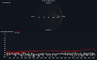
After calibration using the calibration circuits on the board (13,14,15,16) i measured all the circuits. Saved graphs of the measurements are in the table below.
I used the same graphic output for all. I know for some measurements the Smith Chart is the best output, for other other graphs are better, however this was an experiment to test and learn the VNA and compare the circuits.

1LPF-30MHz
2HPF-100MHz
3BPF-433MHz
4BSF-6.5MHz
533 Ω SWR=1.5 
675 Ω SWR=1.5
7
8
9
10
11
 
12
13Short 
14Open 
15Load
16Thru 
17ATT -5dB
18ATT -10dB


Friday, August 26, 2022

Vector Network Analyzer ( VNA) - 2 - Screenshots

During writing of by blog post, that originally was planned as the second post in this VNA series,  i realized that i wanted to show very much pictures in one blog post.
Therefore first this post "Vector Network Analyzer ( VNA) - 2 - Screenshots" with some screenshots of some parts of the VNA software and settings that i used before i will present Vector Network Analyzer ( VNA) - 3 - RF Demo Kit measurements.

The LiteVNA 


Settings I used when testing the RF Demo Kit

Window for Calibration


Frequency ranges (can be stored in the Windows software)


RF Demo Kit

Vector Network Analyzer ( VNA) - 1 - Intro

Recently i received my Vector Network Analyzer (LiteVNA) and am very happy to finally have this interesting device.


Information and explaining in detail what is a VNA, what you can do with it (and how) can be found on internet and is probably better explained by other who have much more experience with this topic. However as i want to post some first results when testing my VNA on my blog, and for visitors of my blog who don't know anything about VNAs i first need do start with "Vector Network Analyzer ( VNA) - 1 - Intro". 

A Vector Network Analyzer (or VNA) is an electronic measurement and testing device that generates and measures frequencies so you can do measurements on things like antennas and (radio) frequency filters.
With modern electronic and some smart people made it possible to buy now a VNA in the 50 Euro range to do some measurement that where some years ago only possible with equipment of thousands of euros. The LiteVNA that i got costs around 100 Euro as this device works up to 6 GHz. My first 3 attempts some months ago to buy a VNA failed. After ordering i received a message it was not possible to deliver and my money was returned. I even did think of buying a VNA with lower frequency range if it was available. However, after some weeks waiting, i tried again at another store and they could deliver relative fast! The VNA came with a Short Open and Load connectors and some cables.

The VNA has two connectors. One connector acts as a combined output and input. A signal is provided to a DUT (Device Under Test)  and the signal is measured. The frequency of the signal can sweep in a frequency range and this way you can determine frequency characteristics of an antenna.
The other connector can act as input and by placing a DUT (a filter circuit) between the output and input you can observe how the DUT (filter circuit) behaves at different frequencies.

Calibration of the VNA is very important and the VNA also reacts on other changes e.g. cable length. A common calibration is the SOLT calibration  (Short, Open, Load and Thru).
Short Open and Load calibration is done by using a shorted circuit, open circuit or a load (e.g. 50 Ohm) on the combined input/output and running the appropriate calibration.
Calibration of Thru is done by connecting the two connectors without the DUT running the Thru calibration.

The LiteVNA can be used stand alone (powered provided by build in Lithium power cell) or via USB connected to a computer. Usng the computer you have a much bigger screen and you can easy export the measured data or  the pictures. The LiteVNA also as a memory slot for additional storage.
As recommended by some internet tutorial I placed additional connectors on the original connectors for protection.

In my next blog post i will post some results using a RF Demo Kit board. 

Some findings in the limited time that i have played with the VNA:

  • It is nice that the PC software can display a graph of the battery power of the VNA.
  • The LiteVNA (at least mine) can become very warm. Perhaps some settings (output power) can or need to be adapted to reduce this. I could not yet find if the temperature can be monitored (like the battery power). I don't know if and and how measurements are influenced by this temperate.
  • Measurements seems to be quite sensitive to things like cable length and the connection.