It has a reset button and two other push buttons several other sensors.There are some Dupont pins available to add something of your own (e.g. an IR led).
 Perhaps in the future i will post some code examples and experiments you can do with this shield. With the LM35 i did not play before. Also i did read about some problems with the Infrared led on a version of this shield. So i hope i will find time soon to play with this board.
| D0 | ( RX see below ) |
| D1 | ( TX see below ) |
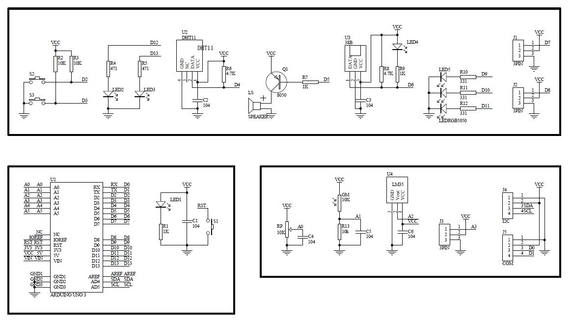
| D2 | SW1 (push button) |
| D3 | SW2 (push button) |
| D4 | DHT11 |
| D5 | Buzzer |
| D6 | IR receiver |
| D7 | (pins with D7 VCC GND) |
| D8 | (pins with D7 VCC GND) |
| D9 | RGB led (R?) |
| D10 | RGB led (R?) |
| D11 | RGB led (R?) |
| D12 | Led Red D1 |
| D13 | Led Blue D2 |
| A0 | Rotation (pot) |
| A1 | LDR (Light sensor) |
| A2 | LM35 (temeprature sensor) |
| A3 | (pins with A3 VCC GND) |
| A4 | ( I2C SDA see below ) |
| A5 | ( I2C SCL see below ) |
| SDA SCL | (pins GND VCC SDA SCL) |
| TX RX | (pins with TX RX VCC GND) |
| Reset | Reset button |
| (power) | Power Led |
Some names that i have seen for this shield are
Easy module shield
Multifunction (multisensor) Shield Arduino Uno
Multifunction DHT11 LM35 Temperature Humidity Easy Module Shield for Arduino UNO
Multifunction Expansion Board DHT11 LM35 Temperature Humidity For Arduino UNO
The interesting of this relative cheap board is that it contains several hardware items to play with as an Arduino shield so you do not need to wire these components.
Schematics and some examples can be found at http://www.getmicros.net/a-look-at-the-easy-module-shield-for-arduino.php
As i have seen several times interesting information disappear i placed a copy of the schematics here on my blog. (For the code there are also other resources).