Friday, November 25, 2022

RF Testboard

To experiment with RF and a VNA a clever designed test-board kit exists so i ordered one.


https://www.sdr-kits.net/DG8SAQ-VNWA-Testboard-kit


Below a description of the connections

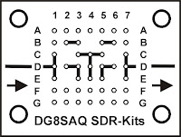
RF testboard connections

Row A, F, G, B1 and B7 are all GND (In picture 2 presented as small circles)
Pad B4 C2 C6 E2 and E6 are Isolated (floating) pads (Not drawn in picture 2) 
The other connections between the pads are as drawn above.

Besides the PCB with the headers some jumpers and a 50 Ohm load is needed.
As a minimum it is recommended to make

2 pcs 2-pin short 
1 pcs  3 pin short
1 pcs  3 pin jumper
1 pcs 50 ohm load
Also having a 2-pin open as reference can be useful

The 50 Ohm load can be made by using 2 100 Ohm 0603 or 0805 SMD resistors in parallel (Stacked on each other). 

To make a through connection between the two SMA connectors place
2-pin shorting jumpers between D1-D2 and D6-D7 and a 3 pin jumper between D3-D5

A short or load (or open) can e.g. be made by placing appropriate components between E1 and F1

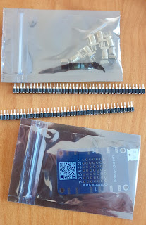
Below a picture of the kit that i did buy. It comes with the header pins and SMA connectors and 2 SMA resistors. 

I did solder the headers on the PCB and also the SMA connectors.
For the connections i first wanted to experiment with standard Dupont connectors and two "normal" 100 Ohm resistors. I know the quality would be better (and better usable at higher frequencies) if i would made it smaller, however i first wanted to get some experience and learn from the results.
I measured some of my resistors, trying to match 2 resistors to get close to 50 Ohm. However finally i just used two random selected resistors as, when measuring with my ohm meter, my 100 Ohm resistors all seemed to be just below 100 Ohm.
So i needed to use two of these resistors in parallel and the resistance would not be as close to 50 Ohm as i wanted. Using standard resistors on a normal Dupont headers would not be perfect for a 50 Ohm load anyway. To do first experiments at not to high frequencies it worked.

Thursday, November 24, 2022

Big Clive Supercomputer November 2022

After building several 'Big Clive Supercomputers' (Blinking LEDS) i decided to also create a PCB version. On the top are the LEDs and on the bottom SMD resistors. Also there is a two pin Dupont connector. 

PCB Size 10cm*10cm  4 mounting holes, Led matrix 7*7 

I ordered black PCBs using the JLCPCB PCB service.

For the first PCB i used all Red LEDs and no resistors to save components. (i just bridged the resistor connections with some solder) and tested it using my LED tester.

The video below is from my Youtube channel https://youtube.com/shorts/r2JGXvKgrpQ?feature=share

On my Github page  https://github.com/JanJeronimus/CliveLights the Gerber file can be found and also a page with links to my other pages about this project..

Wednesday, November 23, 2022

Geiger counter -1-

I could make some time to build my Geiger counter to measure radioactivity.
For some time i had a kit laying around to build a Geiger counter. The counter can also be interfaced to an Arduino , ESP32 or other system. Standard it has an led and a buzzer to give the typical tick sounds of a Geiger counter. On the PCB are the component numbers.

All different components are in separated parts of a plastic foil with a B(uild) O(f) M(aterials) list as index. 

There was no real guidance for building, however on the BOM is a link to a github page  https://github.com/2969773606 . 
I started with the resistors and after that the capacitors followed by other components. A bit a mix of less fragile to more fragile components and low to higher components compartment by compartment. Each time marking when everything was soldered. For certainty i also tested most of the components before soldering.

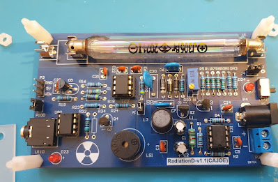
A strange thing is that on the PCB is a component that is not in the box. As i did not see this component soldered on any picture or video about this Geiger counter i expect it was not needed. In the picture of the PCB with components (below) you can see the open position above the radiation symbol.


Also to find the purpose of the potmeter and jumpers you need to look in details on the github page.
The potmeter is used to control the voltage for the Geiger tube. According to this document on github https://github.com/2969773606/GeigerCounter-V1.1/blob/master/En_Calibration_GMv1.1.pdf it is precalibrated and i did not change it (yet).

In the schematic https://github.com/2969773606/GeigerCounter-V1.1/blob/master/Sch__Geiger%20Counter%20Kit-v1.1.pdf you find the jumpers.

 J1 is to disconnect the speaker (buzzer) .  I did not yet play with it,

On Github you find also more information about the Geiger tube, including how to convert measured ticks and examples how to interface with ESP or Arduino. Below a picture of the kit with all the components soldered.

In the Geiger counter kit is a battery holder, and audio connector cable, a 5V USB cable, a plastic shield, some metal and plastic stands. 

When i finished building and checked the PCB i powered it up using the USB cable in a USB power supply and i did hear some random radioactivity ticks. This is the standard background radiation and also some background noise from the tube. And yes it works with the open position for a component above the radiation symbol.

As for the Geiger Tube high voltages are used i switched off the system and added the protection shield using the plastic stands. (I don't like the metal stands for this). I also want to add some protection to the bottom (perhaps using some plywood using more plastic stands as i expect the high voltages will also be at the bottom of the PCB. 


I don't know yet when i will write and post Geiger counter -2- . Perhaps after some experiments with interfacing this counter to an Arduino or ESP and measuring some radiation. 

Tuesday, November 22, 2022

RJ45 to Dupont

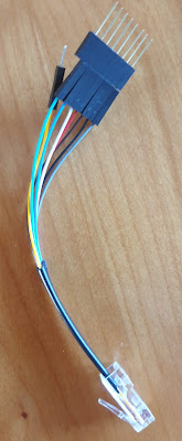
Made this weekend a RJ45 to Dupont connector. This to easy test and use RJ45 wires also for other purposes.

To test  RJ45 Ethernet connectors and wires i already have a nice Ethernet and wire tester. Sometimes you want to connect something else to your Ethernet wiring that does not have a proper RJ45 plug. I wanted to be able to change the order of the pins therefore i used i pin Dupont connectors. 
Afterwards i realized that it would be nice if i could easy put them in the correct order. Therefore i should have added first a 'dummy' empty 8 pin Dupont housing after putting the one pin Dupont pins. Perhaps a next time.
For now i added a log 8 pin female/male Dupont header together with this cable in my toolbox. 


Tuesday, November 1, 2022

Mailbag - October 2022


 My maibag blog post with some of the items i received in October 2022 (including a disclosure of what i want to do with it in the future and some results of a LoRa antenna i received).

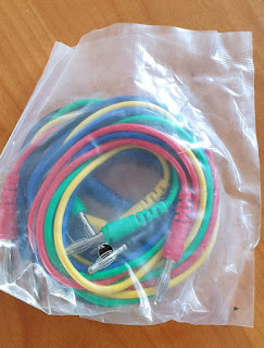
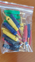
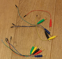
For the cables i did buy 3 sets of these cables with banana-plugs. 
After receiving i noticed that i did not ordered exactly what i wanted as the banana-plugs don't have an option to attach another cable (e.g. in parallel) as they don't have a female connection hole. However this would only be a nice to have as is don't often need this. The wires are flexible and look good.


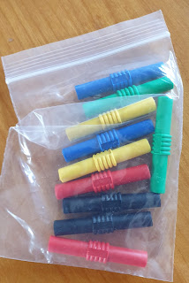
To extend the cables above i also ordered some female to female banana connectors.


Both of the above mentioned products (cables and conenctors) are ordered as my long term plan is to have a better experimenting area. I want to make there some fixed color coded connections with banana chassis plugs (that i already ordered some time ago) between some fixed locations using the same color coding. So this i can use for wiring the first and last meters.
An additional memory card was also needed


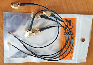
As i had some troubles with my SMA to IPX connection cables when using my self soldered IPX connectors i needed to order some new additional cables.


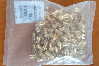
Also some more SMA connectors for RF experiments. If is a big bag as, after some disappointing experiments, i decided that it was probably better to use SMA connectors than the small IPX connectors so i need a lager stock of this connectors.
Also for RF experiments 2 different sized longer coax wires (10m and 5 m) with SMA M to SMA F  connectors.

After some other experiments i expect i will use it for outdoor antenna experiments.
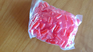
To protect the SMA connectors i also ordered this protection caps

As my last test with my VNA showed that my Lora antenna showed was not for 868 MHz i ordered a new one. Below text from the advertisement:
  Item specifics
  • Brand Name: QKZ
  • Origin: Mainland China
  • Gain(dB): 12dBi
  • Model Number: Aerial Antenna
  • Certification: None
  • Product Description
  Feature
  • 868MHz LoRa LoRaWAN Helium 12dBi RP SMA Male Aerial Antenna.
  • High Efficiency
  • Far Transmission
  • High Strength reinforced Plastic
  • High Density/Light Weight
  • Suitable for Miner (Recommended by Helium):
  • Bobcat/Nebra (Indoor/Outdoor)/RAK Wireless/RAK2 Wireless/Syncrobit/Cal-Chip/LongAP/Sensecap/Kerlink
  Specification
  • Connector: SMA-Male
  • Polarization: Vertical Polarization
  • Gain: 12dBi
  • V.S.W.R: <=1.5
  • Impedance: 50 ohm
  • Material: ABS
  • Operation Temperature: -40~+85 Celsius
  • Length:37.5cm
  • Relative Humidity: Up to 95
My photo of the antenna

I did a quick first test with my Lite VNA and this are the first results (not full optimal, however better than i had before)

The best SWR seems to be around 800MHz with a value around 1.5
At the 868 MHz LoRa frequency the SWR is around 2.3
(On Aliexpress the seller mentioned V.S.W.R: <=1.5 )
When the antenna is somewhere else positioned with a decent ground perhaps my measured  values can change a little.
I ordered also some other SMA connectors. This ones are round chassis types and fit in a hole. 


Monday, October 31, 2022

PCB 'Boat' with led lights

During a recent event i did see this DIY kit for small boat.
It is intended for water scouts, however i  could not resist to buy it as it looks very nice and costs only a few euro's.
I did not opened the package or assembled it yet, so this is more like an 'Mailbag' object, that i did not got via mail. However if you like it, it can be ordered over internet.
The (led) lights can be controlled with the two pushbuttons or by touching the metal contacts near the helm with wet fingers.

https://kitbuilding.org/index.php?option=com_virtuemart&view=productdetails&virtuemart_product_id=114&virtuemart_category_id=24&lang=nl


Wednesday, October 12, 2022

Using IPX connectors

For my VNA i have a RF demo kit using IPX connectors. I wanted to see how easy or difficult it is to use this small IPX connectors for my own projects, so i ordered some and also some PCBs at JLCPCB 


The first connector i soldered was a failure. Measuring with my ohm meter gave a short circuit. However the next attempts went a lot better. I first tinned the connection pad with alsomost no solder. After that i placed the connector. Heated up the connections and the solder joints were made. Measuring showed they where electrical oke. I got very optimistic and almost was convinced that everything was going more easy than expected.
The only real problem that i did see at that moment was the orientation of the connector. When looking on the top of my (probably to cheap) connector there are 2 possibible orientations that i could not distinguish. And one of them is wrong. So the correct orientation of the connector looked the difficult point. For the rest it was going much more easy than expected. 

Using the connectors showed the real problem. On the RF demo board i had no problem connecting and disconnecting IPX cables. However using my own soldered connectors gave problems when trying to  disconnect the cable. The connector would not detach easy and in some occasion the connector sticked to the cable while detaching from the PCB.

Removing the connector from the cable without the PCB was even more problematic. A part of the connector did stay in the cable part.


I will continue with some experiments using the IPX connectors (that are also a lot cheaper than the SMA connectors,
Perhaps my soldering skills will improve to avoid damaging cables with IPX plugs. However i expect i will more use the SMA connectors and also order more SMA connectors and some additional SMA to IPX cables.


Tuesday, October 4, 2022

Mailbag - September 2022

 My Mailbag from China of September 2022
 ( 04OCT2022 published on my blog)


Some more of this nice and
 cheap cases for my glasses.

 I already did buy
 some however with
sun glasses and computer
 glasses i needed some
 more, also for my family.

PCB antenna

SMA Cables

PCB to play with RF experimenting for my VNA. 


Before using it i need to so some soldering (and also make some additonal Dupont pins with through, open and 50 ohm load to do calibration and use for wiring.

Probably i will make a separate blog post about this experimenting board.


SMA Cables with crocodile clips

Some SMA chassis connectors 

Tuesday, September 27, 2022

Banana - Dupont cables

Received some Banana plugs

Banana plugs
and created some cables with Dupont connectors 
Dupont - banana cables

What i don't like at the banana plugs that i received is the lack contrast between the black and blue plugs.

Wednesday, September 21, 2022

Audio transformer - breadboard friendly

Some time ago i ordered some cheap 600:600 ohm audio transformers to use them for some experiments. To easy wiring up an experiment it is possible to plug a transformer direct in a breadboard. The audio transformers fit exactly in a 3*4 grid on a breadboard. (With normal mains transformers I would not recommend this as i don't think it is safe to use high voltages or mains on a breadboard.)
I liked to make a more breadboard friendly version to handle the little transformer more easy, make it easy to move the transformer to other places on the breadboard and have the connections always at the same distances and also get somewhat more robust pins.

 A special PCB for the transformer could have been created, however i still had some 8 pin SMD PCBs and i realized they can be easy adapted for this transformers. This are small PCBs, normally used for 8 pin SMD ICs to making through hole compatible (or make them usable on a breadboard).

At the copper connections for the 8 pin SMD IC some connections were made:  pin 1 to 2 , 3 to 4 , 5 to 6 and 7 to 8. A small wire with some solder to bridge the gaps was used as solder alone tended to flow back on the pads. When you want a connection it sometimes does not work and when you don't want a connection.... 
The wires of the audio transformer fit exactly as 3*4 grid in pin holes 2, 4, 5, and 7. However first the Dupont male pins at pin 1, 8, 3 and 6 (see photos) were soldered as soldering the transformer first would make it more difficult.
For stability 2 strips with 4 male Dupont pins were used, first removing the middle 2 pins as they are not needed.  
1234


8765
The green positions are wires for the audio transformer and at the red positions are for the Dupont pins.  As there are connections between pin 1-2 , 3-4 , 5-6 and 7-8 the transformer is now breadboard friendly.
(Picture with breadboard, a breadboard friendly and a direct plugged in audio transformer and some other components)

Thursday, September 8, 2022

Vector Network Analyzer ( VNA) - 4 - Testing a 'Lora' antenna

With my Vector Network Analyzer i decided to test a LoRa antenna that i had still in a part box as i was never successful in using it.
In my region the Frequency for Lora is 868MHz (and so is my Lora hardware).
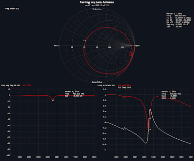
However using  my VNA i found out relative easy that this antenna would be more successful in the 433 MHz region and would not be very useful at 868 MHz ! 

 VNA measurement
This explained why i never had any good results using this antenna !
I expect this antenna was listed a LoRa antenna when i did buy it, however not for my region.


Saturday, September 3, 2022

Non sequential computing environment and Forth -2-

In part -1- of this series this table was presented to to show some Forth words.
The header part of the table is in bold.

Table 1
  TOS n1  n2 n3 
 SWAP  TOS n2 n1 n3
 DROP TOS - 1 
 n2  n3
  + TOS - 1
 n1 + n2  n3

This table is not (yet) a real Forth table and also can be simplified.
Calculations in this table are 'normal algebra' and not in Forth RPN calculations.
'Normal algebra' n1 + n2 becomes in RPN  n1 n2 + 
As already mentioned in my previous post the change of TOS depends on the amount of bits. The TOS should perhaps should be decremented by 2 or another value depending on the amount of bits in each stack item and the memory width.  It is a system constant depending on the implementation.
In this article series i will use SWDTH (stack width). In the RPN table  TOS - 1 should be written as TOS  SWDTH -

Table 2
  TOS n1  n2 n3 
 SWAP  TOS n2 n1 n3
 DROP TOS SWDTH -
 n2  n3
  + TOS SWDTH - 
 n1 n2 +   n3

Some things in this table are still confusing (however it looks already more Forth).
For example a 'strange historical convention' of n1 n2 n3 where
n1 is the item on top of the stack,  n2 is the item just below it and n3 is two steps below. Another way is to see n1 n2 n3 as memory locations where values calculated are stored.  n1 is TOS @ and n2 is TOS SWDTH - @

Table 3
  TOS n1  n2  n3 
  TOS TOS @  TOS SWDTH - @  TOS SWDTH 2* - @ 
 SWAP  TOS n2 n1 n3
 DROP TOS SWDTH -
 n2  n3
  + TOS SWDTH - 
 n1 n2 + n3

In a real 'physical' implementation of the table it would be needed to include items above the TOS (Top Of the Stack) in case items are added or pushed to the stack. Also it would be strange to represent the first items above the stack using n0 . It would be more systematic if the item on top of stack was referenced as n0 and use n+1 and n-1 for the items just above or below. However in Forth for many years items on the stack where called n1 n2 n3 and breaking with this convention would cause a lot of confusion. Also we do not want tot use complicated difficult to read terms as TOS @ or TOS SWDTH - @  So i decided (temporary) to use p0 and not n1 see tabel below.

Table 4

TOS ( n0 ? )n1n2n3

TOSp1p0p-1p-2

TOSTOS SWDTH + @TOS @TOS SWDTH - @TOS SWDTH 2* - @
SWAPTOS
n2n1n3
DROPTOS SWDTH -

n2n3
+TOS SWDTH -

n1 n2 +n3

In the next evolution of the table i added an example of a Forth word that pushes a value to the stack.
It is the Forth word 0 . It is a number implemented in this Forth table where the value 0 is pushed to the stack.
In the table header a new Forth word PA is introduced ( shorthand for ParameterStackAddress ).
The location is described using Forth word  PA to avoid using n1 n2 n3 or p0 p1 p2 notations, 

 : PA SWDTH * TOS @ + ;

Table 5

TOS ( n0 ? )n1n2n3


p1p0p-1p-2
Location TOS1 PA0 PA-1 PA-2 PA

TOSTOS SWDTH + @TOS @TOS SWDTH - @TOS SWDTH 2* - @
SWAPTOS
n2n1n3
DROPTOS SWDTH -

n2n3
+TOS SWDTH -

n1 n2 +n3
0TOS SWDTH +0n1n2n3

We now have almost everything described in Forth and RPN
To evolve the table further we need to do something with the gaps (empty spaces).

In fact there are several options to handle these gaps.
A) Handle a gap as something that not needs to be changed  ( "Ignore" or "don't change" )

Table 6a

TOS ( n0 ? )n1n2n3


p1p0p-1p-2
LocationTOS1 PA0 PA-1 PA-2 PA

TOSTOS SWDTH + @TOS @TOS SWDTH - @TOS SWDTH 2* - @
SWAPTOSIgnoren2n1Ignore
DROPTOS SWDTH -IgnoreIgnoreIgnoreIgnore
+TOS SWDTH -IgnoreIgnoren1 n2 +Ignore
0TOS SWDTH +0IgnoreIgnoreIgnore

B) Fill gap with a "Null" value
"Null" is a special marker and keyword indicating that something has no value (in SQL )
Using  option 2 ( Null) the small table the table would look as below.

Table 6b

TOS ( n0 ? )n1n2n3


p1p0p-1p-2

TOS1 PA0 PA-1 PA-2 PA

TOSTOS SWDTH + @TOS @TOS SWDTH - @TOS SWDTH 2* - @
SWAPTOSNulln2n1n3
DROPTOS SWDTH -NullNulln2n3
+TOS SWDTH -NullNulln1 n2 +n3
0TOS SWDTH +0n1n2n3

Both representations have advantages and disadvantages.
I like option B) using Null as this removes garbage (data that is no longer needed) from the system. Keeping items in a system that are no longer needed can introduce errors and vulnerabilities,

C) A third option could be using Null and, when no changes are needed use some kind of Noop  (no operation, do nothing) indicator.

Table 6c

TOS ( n0 ? )n1n2n3


p1p0p-1p-2

TOS1 PA0 PA-1 PA-2 PA

TOSTOS SWDTH + @TOS @TOS SWDTH - @TOS SWDTH 2* - @
SWAPNoopNulln2n1Noop
DROPTOS SWDTH -NullNullNoopNoop
+TOS SWDTH -NullNulln1 n2 +Noop
0TOS SWDTH +0NoopNoopNoop

If Null and Noop are Forth words a table can be created that describes Forth words in Forth code. The Noop has as disadvantage that just rewriting the old value perhaps is as fast or even faster then  evaluating that something is a Noop and not changing a value.

Table 7

TOS ( n0 ? )n1n2n3


p1p0p-1p-2

TOS1 PA0 PA-1 PA-2 PA

TOSTOS SWDTH + @TOS @TOS SWDTH - @TOS SWDTH 2* - @
SWAPNoopNull-1 PA0 PANoop
DROPTOS SWDTH -NullNullNoopNoop
+TOS SWDTH -NullNull0 PA -1 PA +Noop
0TOS SWDTH +0NoopNoopNoop

Extending the table with more Forth words gives the next table (Table 8)

Table 8

TOS ( n0 ? )n1n2n3


p1p0p-1p-2

TOS1 PA0 PA-1 PA-2 PA

TOSTOS SWDTH + @TOS @TOS SWDTH - @TOS SWDTH 2* - @
SWAPNoopNull-1 PA0 PANoop
DROPTOS SWDTH -NullNullNoopNoop
+TOS SWDTH -NullNull0 PA -1 PA +Noop
0TOS SWDTH +0NoopNoopNoop
1TOS SWDTH +1NoopNoopNoop
2TOS SWDTH +2NoopNoopNoop
3TOS SWDTH +3NoopNoopNoop
4TOS SWDTH +4NoopNoopNoop
-1TOS SWDTH +-1NoopNoopNoop
-2TOS SWDTH +-2NoopNoopNoop
NoopNoopNoopNoopNoopNoop
-TOS SWDTH -NullNull0 PA -1 PA -Noop
*TOS SWDTH -NullNull0 PA -1 PA *Noop
/TOS SWDTH -NullNull0 PA -1 PA /Noop
=TOS SWDTH -NullNull0 PA -1 PA =Noop
@NoopNull@NoopNoop
!TOS SWDTH -NullNullNullNoop
2*NoopNull2 *NoopNoop
2*NoopNull2*NoopNoop
TOSTOS SWDTH +TOSNoopNoopNoop
TOSTOS SWDTH +"Value"NoopNoopNoop
SWDTHTOS SWDTH +"Value"NoopNoopNoop
SWDTH+NoopNullNoopNoopNoop
SWDTH-NoopNullNoopNoopNoop

In the last part of table 8 some issues can be seen that need (and can) be solved.  Therefor i did write it in Italics and some words i described in multiple ways.

! Can't be full described in this table.The result of ! will be that 2 items are removed from the stack. An address and a value. The value will be stored at the address. However it is not easy to extend the lookup table so it will include all addresses in memory. ( @ can be described in the table. However there must be some kind of low level implementation!)

2* multiplies the value that is on top of stack by two. It can be described as just doing 2 *
Written in Forth code : 2* 2 * ;  
However in some Forth systems this is implemented in low level code as it can be executed fast,  This is just one example, however in general this creates a dilemma when trying to make a table like this. Many Forth words can easy be defined as itself, However that does not explain what these Forth words do. Also sometimes these words can be implemented in another way using other Forth words or should  call low level code.  

TOS ( Top Of Stack) is a variable. It it can be put in the table just calling some implementation of itself. However an easy implementation is pushing 'the value of the address' on the stack.

 SWDTH is a (system) constant, as described in the beginning of this article. A constant can be described in this table as it self, Or just put the value on the stack comparable to TOS

Some sequences of operations appear very often in this table. Examples are
TOS SWDTH + and TOS SWDTH + and also my new Forth word PA
  : PA SWDTH * TOS @ + ;
This indicates that speeding up these sequences can speed up the Forth system. 

We have seen that we can put the descriptions of (several) Forth words in a table.
Can that help us in a new Forth implementation and what about a 'Non sequential computing environment'? Yes, if we can describe Forth words in a table we can describe Forth in a table. This not only makes Forth portable, it also makes it possible we can create Forth in a table environment, e.g. a relational database.

Tuesday, August 30, 2022

P0cForth

What is P0cForth?

P0cForth is NOT another (full) Forth implementation. It is a only minimalistic Forth like system and my idea about P0cForth, I respect other ideas about minimalistic Forth and even opinion that this is so minimal that it is not a real Forth system. That is why it has a 0 in it name.
Why P0cForth?

For a long time I was thinking what Forth words are minimal needed to code to create a Forth (like) system. There are guides what Forth primitives need to be created to bootstrap a full Forth system. However I wanted a minimalist set of Forth words. Not to bootstrap a Forth system, only as a proof of concept for a Forth system that can be extended. A search on internet gives information about several interesting minimal Forth systems. Even systems minimal systems including @ ! however that is not what i wanted.
Also wanted to give it a name. I decided for P0cForth , "Proof of concept Forth" , i changed the o to 0.
It is to have bare minimal system that is relative easy to build (and can be extended) to have a proof of concept Forth system. 

What words/code need to be in P0cForth?

In the Forth2020 Zoom meeting on 9 januari 2021 Dr Ting talked about  Jeforth 2.01.
He mentioned a minimal system with 9 Forth words
: ; * . , dup dolit ret here
He also presented simple demos:
: square dup * ;
: quad square square ;
; octet quad quad ;
8 octet . 4 octet .

I used this 9 words as a start for P0cForth., However, I want to

reduce it even more.

So I ended up with this 5 words:
: ; * . dup 
I decided to reduce the system even more by omitting the interpretation of numbers defining (some) numbers direct as words. This would decrease the programming code and logic. And yes when extending the proof of concept Forth real handling of numbers would be useful and literals and dolit can be very useful. However I wanted to reduce it as much as possible. Literals are a very useful method of implementation, however i did not want to force this as a solution for handling numbers in my definition of P0cForth.
The code created for a number as a Forth words for a target system can be easy copied and adapted for another number. So it could be easy extended to include a lot of other numbers. However i wanted it to  as minimal as possible.
What numbers would be needed  minimal to have a proof of concept Forth system? At first did think at a minimum i would be needing the numbers 0 1 2 3 and (perhaps) -1 With this numbers you can play in the minimal PocForth for testing. And these numbers could be included in the dictionary.
With * and -1 it can be  and easy extend it to numbers in the range -4 to 4 (However if you continue reading to the end you will see this idea was wrong. Only one very special number is sufficient to create all numbers!)
: 4 2 2 * ;
: -2 -1 2 * ;
: -3 -1 3 * ;
: -4 -1 4 * ;
Also the demo mentioned above can be tested (after creating 8)
: 8 4 2 * ;
: square dup * ;
: quad square square ;
; octet quad quad ;
8 octet . 4 octet .

Adding code for a + function would make it possible to extend the number range even further without having gaps.

My first idea of a minimal P0cForth that could be a first start for a minimal Forth as
5 Forth words                 : ; * . dup
5 ‘number words’           -1 0 1 2 3

Creating e.g. a text input stream processor with this 6 different type of words would give a proof of concept system that could be used as a basis to create a full Forth system. 

Two facts made me not complete happy with this set of words.
- The possibility to build a complete Forth with these words is missing. it is only possible to extend this Forth by changing the 'external' code and add more words. However this minimal words can be a good basis of a proof of concept when creating a new Forth.
- And most important I did think it would be possible to reduce this word set even more!
So i started to reducing
1 is not needed as it could be defined by the other words
: 1 -1 dup * ;
If i would add the Forth word + 2 and 3 can be removed 
: 2 1 dup + ;
: 3 1 dup dup + + ;
Also 0 is not needed as it can be created
: 0 -1 1 + ; 
: 0 -1 dup dup * + ;
I would never have imagined that it was only needed to have one number to create other numbers, and that that number would be -1  

P0cForth minimal wordset 
No interpretation of numbers needed and only 7 words 
:  ;  .  *  dup  +  -1

Here some demo code to demonstrate what can be done with this 7 word system
: 0 -1 dup dup * + ;
: 1 -1 dup * ;
: 2 1 dup + ;
: 3 1 dup dup + + ;
: 4 2 dup * ;
: 8 4 2 * ;
: - -1 * + ;
: square dup * ;
: quad square square ;
: octet quad quad ;
3 square .
8 octet . 
4 octet .
8 3 - .
I think it is possible to reduce this 7 word set even more or add more capabilities adapting the selection of this words.
A simple option would be to reduce the word set would be omitting ; and have a the new definition, that in Forth starts with the colon :  close always at the end of the line.

Sunday, August 28, 2022

Vector Network Analyzer ( VNA) - 3 - RF Demo Kit

To get to know my VNA i used my RF Demo kit that i already received some weeks ago.
The RF Demo kit board has 18 circuits, including circuits that can be used for calibration ( Short, Open Load and Thru).

I configured some parameters in my LiteVNA ( 0.1 MHz - 450 MHz , for more details see screenshot my previous post about my VNA. ) It are not the optimal settings to test a specific circuit, however this are settings to measure all the circuits on this RF Demo Kit within a reasonable time.

After calibration using the calibration circuits on the board (13,14,15,16) i measured all the circuits. Saved graphs of the measurements are in the table below.
I used the same graphic output for all. I know for some measurements the Smith Chart is the best output, for other other graphs are better, however this was an experiment to test and learn the VNA and compare the circuits.

1LPF-30MHz
2HPF-100MHz
3BPF-433MHz
4BSF-6.5MHz
533 Î© SWR=1.5 
675 Î© SWR=1.5
7
8
9
10
11
 
12
13Short 
14Open 
15Load
16Thru 
17ATT -5dB
18ATT -10dB