Friday, November 25, 2022

RF Testboard

To experiment with RF and a VNA a clever designed test-board kit exists so i ordered one.


https://www.sdr-kits.net/DG8SAQ-VNWA-Testboard-kit


Below a description of the connections

RF testboard connections

Row A, F, G, B1 and B7 are all GND (In picture 2 presented as small circles)
Pad B4 C2 C6 E2 and E6 are Isolated (floating) pads (Not drawn in picture 2) 
The other connections between the pads are as drawn above.

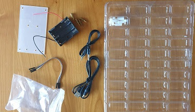
Besides the PCB with the headers some jumpers and a 50 Ohm load is needed.
As a minimum it is recommended to make

2 pcs 2-pin short 
1 pcs  3 pin short
1 pcs  3 pin jumper
1 pcs 50 ohm load
Also having a 2-pin open as reference can be useful

The 50 Ohm load can be made by using 2 100 Ohm 0603 or 0805 SMD resistors in parallel (Stacked on each other). 

To make a through connection between the two SMA connectors place
2-pin shorting jumpers between D1-D2 and D6-D7 and a 3 pin jumper between D3-D5

A short or load (or open) can e.g. be made by placing appropriate components between E1 and F1

Below a picture of the kit that i did buy. It comes with the header pins and SMA connectors and 2 SMA resistors. 

I did solder the headers on the PCB and also the SMA connectors.
For the connections i first wanted to experiment with standard Dupont connectors and two "normal" 100 Ohm resistors. I know the quality would be better (and better usable at higher frequencies) if i would made it smaller, however i first wanted to get some experience and learn from the results.
I measured some of my resistors, trying to match 2 resistors to get close to 50 Ohm. However finally i just used two random selected resistors as, when measuring with my ohm meter, my 100 Ohm resistors all seemed to be just below 100 Ohm.
So i needed to use two of these resistors in parallel and the resistance would not be as close to 50 Ohm as i wanted. Using standard resistors on a normal Dupont headers would not be perfect for a 50 Ohm load anyway. To do first experiments at not to high frequencies it worked.

Thursday, November 24, 2022

Big Clive Supercomputer November 2022

After building several 'Big Clive Supercomputers' (Blinking LEDS) i decided to also create a PCB version. On the top are the LEDs and on the bottom SMD resistors. Also there is a two pin Dupont connector. 

PCB Size 10cm*10cm  4 mounting holes, Led matrix 7*7 

I ordered black PCBs using the JLCPCB PCB service.

For the first PCB i used all Red LEDs and no resistors to save components. (i just bridged the resistor connections with some solder) and tested it using my LED tester.

The video below is from my Youtube channel https://youtube.com/shorts/r2JGXvKgrpQ?feature=share

On my Github page  https://github.com/JanJeronimus/CliveLights the Gerber file can be found and also a page with links to my other pages about this project..

Wednesday, November 23, 2022

Geiger counter -1-

I could make some time to build my Geiger counter to measure radioactivity.
For some time i had a kit laying around to build a Geiger counter. The counter can also be interfaced to an Arduino , ESP32 or other system. Standard it has an led and a buzzer to give the typical tick sounds of a Geiger counter. On the PCB are the component numbers.

All different components are in separated parts of a plastic foil with a B(uild) O(f) M(aterials) list as index. 

There was no real guidance for building, however on the BOM is a link to a github page  https://github.com/2969773606 . 
I started with the resistors and after that the capacitors followed by other components. A bit a mix of less fragile to more fragile components and low to higher components compartment by compartment. Each time marking when everything was soldered. For certainty i also tested most of the components before soldering.

A strange thing is that on the PCB is a component that is not in the box. As i did not see this component soldered on any picture or video about this Geiger counter i expect it was not needed. In the picture of the PCB with components (below) you can see the open position above the radiation symbol.


Also to find the purpose of the potmeter and jumpers you need to look in details on the github page.
The potmeter is used to control the voltage for the Geiger tube. According to this document on github https://github.com/2969773606/GeigerCounter-V1.1/blob/master/En_Calibration_GMv1.1.pdf it is precalibrated and i did not change it (yet).

In the schematic https://github.com/2969773606/GeigerCounter-V1.1/blob/master/Sch__Geiger%20Counter%20Kit-v1.1.pdf you find the jumpers.

 J1 is to disconnect the speaker (buzzer) .  I did not yet play with it,

On Github you find also more information about the Geiger tube, including how to convert measured ticks and examples how to interface with ESP or Arduino. Below a picture of the kit with all the components soldered.

In the Geiger counter kit is a battery holder, and audio connector cable, a 5V USB cable, a plastic shield, some metal and plastic stands. 

When i finished building and checked the PCB i powered it up using the USB cable in a USB power supply and i did hear some random radioactivity ticks. This is the standard background radiation and also some background noise from the tube. And yes it works with the open position for a component above the radiation symbol.

As for the Geiger Tube high voltages are used i switched off the system and added the protection shield using the plastic stands. (I don't like the metal stands for this). I also want to add some protection to the bottom (perhaps using some plywood using more plastic stands as i expect the high voltages will also be at the bottom of the PCB. 


I don't know yet when i will write and post Geiger counter -2- . Perhaps after some experiments with interfacing this counter to an Arduino or ESP and measuring some radiation. 

Tuesday, November 22, 2022

RJ45 to Dupont

Made this weekend a RJ45 to Dupont connector. This to easy test and use RJ45 wires also for other purposes.

To test  RJ45 Ethernet connectors and wires i already have a nice Ethernet and wire tester. Sometimes you want to connect something else to your Ethernet wiring that does not have a proper RJ45 plug. I wanted to be able to change the order of the pins therefore i used i pin Dupont connectors. 
Afterwards i realized that it would be nice if i could easy put them in the correct order. Therefore i should have added first a 'dummy' empty 8 pin Dupont housing after putting the one pin Dupont pins. Perhaps a next time.
For now i added a log 8 pin female/male Dupont header together with this cable in my toolbox. 


Tuesday, November 1, 2022

Mailbag - October 2022


 My maibag blog post with some of the items i received in October 2022 (including a disclosure of what i want to do with it in the future and some results of a LoRa antenna i received).

For the cables i did buy 3 sets of these cables with banana-plugs. 
After receiving i noticed that i did not ordered exactly what i wanted as the banana-plugs don't have an option to attach another cable (e.g. in parallel) as they don't have a female connection hole. However this would only be a nice to have as is don't often need this. The wires are flexible and look good.


To extend the cables above i also ordered some female to female banana connectors.


Both of the above mentioned products (cables and conenctors) are ordered as my long term plan is to have a better experimenting area. I want to make there some fixed color coded connections with banana chassis plugs (that i already ordered some time ago) between some fixed locations using the same color coding. So this i can use for wiring the first and last meters.
An additional memory card was also needed


As i had some troubles with my SMA to IPX connection cables when using my self soldered IPX connectors i needed to order some new additional cables.


Also some more SMA connectors for RF experiments. If is a big bag as, after some disappointing experiments, i decided that it was probably better to use SMA connectors than the small IPX connectors so i need a lager stock of this connectors.
Also for RF experiments 2 different sized longer coax wires (10m and 5 m) with SMA M to SMA F  connectors.

After some other experiments i expect i will use it for outdoor antenna experiments.
To protect the SMA connectors i also ordered this protection caps

As my last test with my VNA showed that my Lora antenna showed was not for 868 MHz i ordered a new one. Below text from the advertisement:
  Item specifics
  • Brand Name: QKZ
  • Origin: Mainland China
  • Gain(dB): 12dBi
  • Model Number: Aerial Antenna
  • Certification: None
  • Product Description
  Feature
  • 868MHz LoRa LoRaWAN Helium 12dBi RP SMA Male Aerial Antenna.
  • High Efficiency
  • Far Transmission
  • High Strength reinforced Plastic
  • High Density/Light Weight
  • Suitable for Miner (Recommended by Helium):
  • Bobcat/Nebra (Indoor/Outdoor)/RAK Wireless/RAK2 Wireless/Syncrobit/Cal-Chip/LongAP/Sensecap/Kerlink
  Specification
  • Connector: SMA-Male
  • Polarization: Vertical Polarization
  • Gain: 12dBi
  • V.S.W.R: <=1.5
  • Impedance: 50 ohm
  • Material: ABS
  • Operation Temperature: -40~+85 Celsius
  • Length:37.5cm
  • Relative Humidity: Up to 95
My photo of the antenna

I did a quick first test with my Lite VNA and this are the first results (not full optimal, however better than i had before)

The best SWR seems to be around 800MHz with a value around 1.5
At the 868 MHz LoRa frequency the SWR is around 2.3
(On Aliexpress the seller mentioned V.S.W.R: <=1.5 )
When the antenna is somewhere else positioned with a decent ground perhaps my measured  values can change a little.
I ordered also some other SMA connectors. This ones are round chassis types and fit in a hole.