Wednesday, August 2, 2017

Voice control V3 (Part 1)

An interesting input device is the ElecHouse Voice Recognition Module V3. It comes with a microphone and some pins to solder on the PCB. I ordered my "1set Speed Recognition, Voice Recognition Module V3" module on Aliexpress (between 17 and 18 euro 2017).
Voice Recognizer V3 & Arduino Uno
The question is what can this module do for your projects and how can you use it? The answer is simple: it  can recognize your voice and output a signal depending on the word or short phrase that you have learned the module. The good news is that (according to the spec) you can train this relative cheap module to recognize 80 words or phrases. These words or phrases are stored in memory on the module. The bad news is the module can only recognize 7 different phrases at the same time. And you also need to train the system first with all your phrases.
You can create a system that knows what to do with commands like:

"James light on"
"James light off"
"James light color white"
"James light color green"
"James light color blue"
"James light color yellow"

"James light dim 25"
"James light dim 50"
"James light dim 75"
"James light dim 100"

"James TV off"
"James TV on"
"James TV channel next"
"James TV channel prev"
"James TV channel one"

"James Radio on"
"James Radio off"

And yes, this are much more than 7 phrases! You can do this using a menu structure!

Teach the system all the separate words ("James", "light", "TV" ," Radio" "color" etc.)
Load only the word "James". If the module recognizes "James" load the three words "light" "TV" Radio" if the module recognizes "light", load the words "on" "off" "color" "dim" and build a menu system.
You can get the same (or even better) effect with Amazon Alexa or a Google app on your android. Using this module the voice recognition finds happens inside the module. You do not need internet access and perhaps even more important the privacy: The audio is not transmitted to the internet.

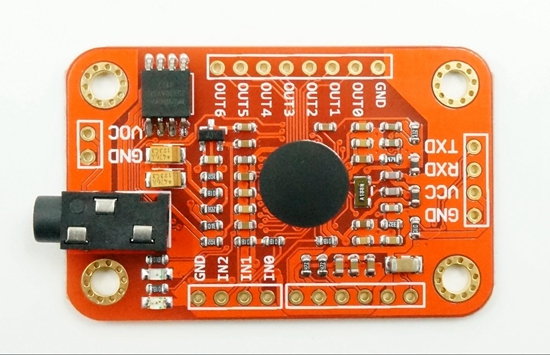
A small disadvantage is that you need to train the module. My first test of the module was with an Ardhuino Uno. The ElecHouse website has a link Arduino library with some examples including a voice training example. Connect GND and VCC (5v) , RXD to Arduino pin 3 and TXD to Arduino pin 2. (If you do not like to use pin 2 and 3 you can use other pins. However you need to make a small change in the software). You only need to connect this four pins on the V3 module (and the included microphone) to a working Arduino to start.

Some info from ElecHouse about the module:
ELECHOUSE Voice Recognition Module is a compact and easy-control speaking recognition board.
This product is a speaker-dependent voice recognition module. It supports up to 80 voice commands in all. Max 7 voice commands could work at the same time. Any sound could be trained as command. Users need to train the module first before let it recognizing any voice command.
This board has 2 controlling ways: Serial Port (full function), General Input Pins (part of function). General Output Pins on the board could generate several kinds of waves while corresponding voice command was recognized.
What's new?
We already have Voice Recognition module V2. It supports 15 commands in all and only 5 commands at the same time.
On V2, voice commands are separated into 3 groups while you training it. And only one group (5 commands) could to be imported into Recognizer. It means only 5 voice commands are effective at the same time.
On V3, voice commands are stored in one large group like a library. Any 7 voice commands in the library could be imported into recognizer. It means 7 commands are effective at the same time.
Parameter
Voltage: 4.5-5.5V
Current: <40mA
Digital Interface: 5V TTL level for UART interface and GPIO
Analog Interface: 3.5mm mono-channel microphone connector + microphone pin interface
Size: 31mm x 50mm
Recognition accuracy: 99% (under ideal environment)
Feature
Support maximum 80 voice commands, with each voice 1500ms (one or two words speaking)
Maximum 7 voice commands effective at same time
library is supplied
Easy Control: UART/GPIO

On internet is a lot more info about this and similar modules. Here is link to a YouTube video : S134 - Voice Recognition Module V3

Tuesday, July 18, 2017

Solar charger teardown

Several YouTube video review channels do sometimes a product teardown. When i ordered two of this Aliexpress i had no plans to do a teardown.
solar chargers at
When i orderd the power banks in february 2017 the Pcs 8000 mah Portable Solar Power Bank waterproof Enternal battery power bank phone charger for Iphone HTC Lenovo Mipad did cost € 6,51 each and i wanted to test them to use them for IOT devices, perhaps outdoor. and low power.


Features (according to seller):
8000mAh solar charger external battery power bank
Build-in 8000mAh lithium polymer battery
Super waterproof and dustproof.
Strong shockproof and drop resistance.
With dual USB and micro USB ports.
Emergency LED torch, the LED flashlight works perfectly in darkness, especially for emergency.
4 LED status of charge indicators indicate the charging and discharging process
Environmentally friendly silica gel and ABS+PC materials, and rubber paint surface process
Compact, portable & stylish design.
Specifications:
Model:S69
Battery Capacity: 8000mAh Li-polymer battery
Solar panel: 5V, 200mA
Power: 4W
Input: DC 5V/ 1A
Output: DC 5V/ 2 x 1A
Product size: 142* 75*13.6mm
Operation Temperature: 0-45 degree
Weight:140 g
Compatible: for iPhone, iPad, Android phone, GPS device, camera (most devices that use a USB cable to charge).
Color: ... (several colors available)

The package included:
1 x Solar Charger
1 x Free carabiner
1 x Micro USB charging cable

Super waterproof and dustproof, strong shockproof and drop resistance. That would be nice for an outdoor IOT application.
( Now in july the seller only has e.g. Vidar waterproof 5000mah solar power bank polymer-Li portable solar charger. I can not find "my" 8000 mah version for a comparable price (yes i found some other 8000 mah power banks.)
One of the solar devices was put in my car under the window. I almost did forget it and now a semi automatic teardown has happened. Due to the heat of the sun one the power banks has opened itself.
Warning on the package!!
It was warm here in the Netherlands, but not extreme hot.
In a car behind the window the temperature can rise quick. In the specs/description an operation temperature of 0-45 degrees is mentioned.
I posted this as a warning do not let the powerbank in your car behind the glass and to show pictures of the solar powerbank and the batteries after further opening it.  One of the batteries has changed of shape and the enclosure can not be closed anymore.

 I did not a complete teardown as i wanted to rescue parts and the enclose. (And perhaps build an IOT device inside it). To look inside i opened it a bit more.  You can see the solar cell, a PCB and two (different) battery packs in parallel. According to the specs these two packs can deliver together the 8000 mah.


Monday, July 17, 2017

Microwave Radar Sensor RCWL-0516 with Arduino Uno

The Microwave Radar Sensor RCWL-0516 is an interesting cheap motion sensor.
At Aliexpress i found 5 pieces for  € 2,19 => € 0,44 / piece.

Info how to wire the device and a test program was found on https://www.14core.com/wiring-the-rcwl0516-auto-induction-doppler-microwave-radar-with-esp826632arduino/

I soldered some wires with Dupont connectors to one of my RCWL-0516 modules and tested the program with an Arduino Uno (clone). Not yet with ESP8266, perhaps that will come in another RCWL-0516 post. It found some little errors that i needed to corrected. When changing the program i also did put the serial output on one line for each change with a millis() timestamp.


The program after my changes:


/* 14CORE | DOPPLER RADAR TEST CODE 
*************************************
From https://www.14core.com/wiring-the-rcwl0516-auto-induction-doppler-microwave-radar-with-esp826632arduino/
Modified
2017 July 17 by @JanJeronimus  / Correction 'bool sens;'& 115200 /  Output one line , added additional and spacesMillis() 
*/
static bool value = -1;
bool sense;

const int8_t Output = 13;
#ifdef ESP8266
const int8_t sensor = D2;
#else
const int8_t sensor = 2;
#endif

void setup(){
Serial.begin(115200);
#ifdef ESP8266
Serial.println(" 14CORE | DOPPLER RADAR TEST CODE");
Serial.println("==================================");
Serial.println("ESP8266 Started......");
digitalWrite(Output,1);
#else
Serial.println("Arduino MCU Started......");
digitalWrite(Output,0);
#endif
pinMode(Output, OUTPUT);
pinMode(sensor, INPUT);
}

void loop(){  
sense = digitalRead(sensor);
if (sense != value){
  Serial.print( millis()); 
  Serial.print(" Raw Value : ");
  Serial.print(sensor);
  Serial.println(sense ? " +HIGH" : " -LOW");   
#ifdef ESP8266
  digitalWrite(Output, ! sense);
#else
  digitalWrite(Output, sense);
#endif
  value = sense;
  }
  delay(20);
}

To use the program you need to connect 3 pins
GND
OUT - connect this to an input pin (Arduino D2)
VIN 4 to 28 volt
It seems the CDS pin can be used to disable detection. You need not to connect it.
The 3V3 pin is for output not input!  (Interesting to try if it can be used to power an ESP8266!)

The sensor works fine and can detect motion even behind obstacles. It can detect motion at about 3 to 4 meter distance.

Some other references

Two videos about the RCWL-0516 by nenioc187 :


Specs & Pin info :
  https://www.elecrow.com/rcwl-0516-microwave-radar-sensor-switch-module-body-induction-module-4-28v-100ma.html

 https://github.com/jdesbonnet/RCWL-0516/

Tuesday, July 11, 2017

TM1638 8 bit digital Led module (1)


On Aliexpress i found this Key Display "For AVR Arduino" "New" 8-Bit Digital LED Tube 8-Bit TM1638 Module. I did put some quotes" in the name as this module is not for Arduino only, it can be used also in projects with other microcontrollers e.g. the ESP8266.
TM1638 module - Front
For this module i payed 2017Q1 only € 1,32 . Relative cheap for a module that only needs 3 lines from your microcontroller and gives you
  • 8 keys
  • 8 LEDs common cathode
  • 8 a digital 7 segment displays
The magic is done using the TM1638 digital tube drive chip.
For the wiring connect VCC GND to a 5V supply and connect STB CLK DIO to the microcontroller IO ports. Scanning display and key scan don't need microcontroller intervention, only need to register to display data related to reading and writing or testing buttons, save MCU resources.
The only disadvantage i found is, when putting this module in an enclosure the female connections pins of this module are pointing to the front. Depending of the enclosure you need to remove, bend or put them on the back side of the module.

I tested it with an Arduino (clone).
Sketch to test the display:
/*
 * Testing the TM1638 board
 Display test:
Programs dislights some leds and display
See code for details
Hardware connections: 
 Arduino              TM1638 based board
 3.3V   ------------------ VCC
 GND    ------------------ GND
 PIN #7 ------------------ STB
 PIN #8 ------------------ DIO
 PIN #9 ------------------ CLK

 Source
 https://blog.3d-logic.com/2015/01/10/using-a-tm1638-based-board-with-arduino/
 8 july 2017  JanJeronimus
*/

const int strobe = 7;
const int clock = 9;
const int data = 8;

void sendCommand(uint8_t value)
{
  digitalWrite(strobe, LOW);
  shiftOut(data, clock, LSBFIRST, value);
  digitalWrite(strobe, HIGH);
}

void reset()
{
  sendCommand(0x40); // set auto increment mode
  digitalWrite(strobe, LOW);
  shiftOut(data, clock, LSBFIRST, 0xc0);   // set starting address to 0
  for(uint8_t i = 0; i < 16; i++)
  {
    shiftOut(data, clock, LSBFIRST, 0x00);
  }
  digitalWrite(strobe, HIGH);
}

void setup()
{
  pinMode(strobe, OUTPUT);
  pinMode(clock, OUTPUT);
  pinMode(data, OUTPUT);

  sendCommand(0x8f);  // activate and set brightness to max
  reset();
}

void loop()
{
  sendCommand(0x44);  // set single address

  digitalWrite(strobe, LOW);
  shiftOut(data, clock, LSBFIRST, 0xc0); // 1st digit
  shiftOut(data, clock, LSBFIRST, 0xff);
  digitalWrite(strobe, HIGH);

  digitalWrite(strobe, LOW);
  shiftOut(data, clock, LSBFIRST, 0xc5); // 3rd LED
  shiftOut(data, clock, LSBFIRST, 0x01);
  digitalWrite(strobe, HIGH);

  digitalWrite(strobe, LOW);
  shiftOut(data, clock, LSBFIRST, 0xcb); // 3rd LED
  shiftOut(data, clock, LSBFIRST, 0x01);
  digitalWrite(strobe, HIGH);

  digitalWrite(strobe, LOW);
  shiftOut(data, clock, LSBFIRST, 0xce); // last digit
  shiftOut(data, clock, LSBFIRST, 0xff);
  digitalWrite(strobe, HIGH);
}

Arduino Uno (clone) with TM1638 display (and key) module.


Sketch to test input keys
./*
 * Testing the TM1638 board
 Button test:
 Progam scans buttons. If button pressed the led over the button will be lit
Hardware connections: 
 Arduino              TM1638 based board
 3.3V   ------------------ VCC
 GND    ------------------ GND
 PIN #7 ------------------ STB
 PIN #8 ------------------ DIO
 PIN #9 ------------------ CLK

 Source
 https://blog.3d-logic.com/2015/01/10/using-a-tm1638-based-board-with-arduino/
 8 july 2017  JanJeronimus
*/

const int strobe = 7;
const int clock = 9;
const int data = 8;

void sendCommand(uint8_t value)
{
  digitalWrite(strobe, LOW);
  shiftOut(data, clock, LSBFIRST, value);
  digitalWrite(strobe, HIGH);
}

void reset()
{
  sendCommand(0x40); // set auto increment mode
  digitalWrite(strobe, LOW);
  shiftOut(data, clock, LSBFIRST, 0xc0);   // set starting address to 0
  for(uint8_t i = 0; i < 16; i++)
  {
    shiftOut(data, clock, LSBFIRST, 0x00);
  }
  digitalWrite(strobe, HIGH);
}

void setup()
{
  pinMode(strobe, OUTPUT);
  pinMode(clock, OUTPUT);
  pinMode(data, OUTPUT);

  sendCommand(0x8f);  // activate and set brightness to max
  reset();
}

uint8_t readButtons(void)
{
  uint8_t buttons = 0;
  digitalWrite(strobe, LOW);
  shiftOut(data, clock, LSBFIRST, 0x42);

  pinMode(data, INPUT);

  for (uint8_t i = 0; i < 4; i++)
  {
    uint8_t v = shiftIn(data, clock, LSBFIRST) << i;
    buttons |= v;
  }

  pinMode(data, OUTPUT);
  digitalWrite(strobe, HIGH);
  return buttons;
}

void setLed(uint8_t value, uint8_t position)
{
  pinMode(data, OUTPUT);

  sendCommand(0x44);
  digitalWrite(strobe, LOW);
  shiftOut(data, clock, LSBFIRST, 0xC1 + (position << 1));
  shiftOut(data, clock, LSBFIRST, value);
  digitalWrite(strobe, HIGH);
}

void loop()
{
  uint8_t buttons = readButtons();

  for(uint8_t position = 0; position < 8; position++)
  {
    uint8_t mask = 0x1 << position;

    setLed(buttons & mask ? 1 : 0, position);
  }
}

Back side
There exists also a library to easy program this module.

Tuesday, July 4, 2017

Lora RFM95 breadboard friendly

The RFM95 LoRa module is standard not breadboard friendly. One of my RFM95 modules was used to make a one channel gateway. See details in a previous post on my blog.
A second module i made breadboard friendly using a 16 pin dip IC socket. The RFM95 module was joined to the IC socket with wires.
From the ground wires only one wire was connected from the dip socket to the three ground connections on the RFM95 module.
The antenna output was not connected to the dip socket. I added a 8,2 cm wire as antenna to this module.
As 3 pins of the 16pin dip socket are not connected to the RFM95 module. (The antenna and 2 of the 3 ground connections) also a 14 pin dip socket can be used.
I used a 16 pin version as this 16 pin socket that i had in stock has a better connection to the breadboard than the 14 pin version.
I have plans to use the 3 spare pins later to add some components. E.g. one pin connected to DIO0, DIO1 and DIO2 with diodes as used in some circuits / one or more leds (power led) or some sensor(s). Before adding this items want to do some tests first on a breadboard.
RFM95 connections
DIO2GND
DIO1MISO
DIO0MOSI
3.3VSCK
DIO4NSS
DIO3RESET
GND(1)DIO5
ANA(2)GND(1)
Not on 16 pin dip:
(1) GND all connected to one GND
(2) Antenna (wire antenna, not to 16 pin socket)

To test this module i wired it to a Wemos D1 mini the same way as my First (One Channel) LoRa Gateway, adapted the sketch (name of gateway/server) and uploaded it.
On the breadboard you can already see some diodes as used in some circuits and also a push button. They are not used in the circuit. Only the wire connections as in my first RFM95 - Wemos D1 mini LoRa gateway where made. This circuit worked just as my first 1CH gateway !!
Connections (for 1CH LoRa gateway):
RFM95 pinWemos D1 mini
(ESP8266) pin
3.3V3.3V
GNDGND
MISOD6 GPIO12/MISO
MOSID7 GPIO13/MOSI
SCKD5 GPIO14/CLK
NSSD8 GPIO15/CS
RESET*nc
DIO0D1, GPIO5
Wemos D1 mini  connected to RFM95 module

Thursday, June 22, 2017

PAM8403_Amplifier

At Aliexpress i ordered 5pcs/lot PAM8403 Super mini digital amplifier board 2 * 3W Class D digital amplifier board efficient 2.5 to 5V USB power supply for 0,87 euro.
That is about 18 euro cents for a stereo amplifier module! This module has no potentiometer to regulate the output volume.
There are also other PAM8403 modules available, some with potentiometer(s).
There are also PAM8403 modules with potentiometer but they are much more expensive ( 0,57 euro )
On one i soldered Dupont connectors for easy access to us it on a breadboard or other temporary experiments. On another i soldered wires to two cheap mini speakers and also some Dupont connectors.


Interesting very cheap
 amplifier !


Wednesday, June 21, 2017

My First Lora Gateway

FRM95
RFM95 back LoRa breakout

As i like doing some projects with IoT i also wanted to experiment with LoRa.
Some time ago i ordered a cheap LoRa shield for my Arduino. Unfortunate i did not get it working. I could not find out if it was something with the code, the jumper settings, a hardware error or perhaps my shield could not reach a LoRa gateway in Almere.
Perhaps in another LoRa post in my blog you will read more about this shield.
RFM95 front LoRa breakout

When asking advice someone was so friendly to send me documentation to make a simple one channel test LoRa gateway with an RFM95 and a Wemos D1 mini.

On Aliexpress i found two RFM95 breakout boards for 13 Euro so i decided to order them. I have done several experiments and projects with different ESP8266 boards but until now i never used the Wemos version.
Between the  RFM95 and the  Wemos D1 mini (ESP8266) you need to make the some connections.
Wemos D1 mini
Wemos D1 mini
According to a descriptions i connected this:
RFM95 pinESP8266 pin
3.3V3.3V
GNDGND
MISOD6 GPIO12/MISO
MOSID7 GPIO13/MOSI
SCKD5 GPIO14/CLK
NSSD8 GPIO15/CS
RESET*nc
DIO0D1, GPIO5

The Wemos D1 mini came with 2 sets of male pins, 2 sets of female pins and 2 sets of female with long male pins. I decided to build the circuit on a small prototype PCB board. (It is also possible to order a Wemos PCB for the RFM95 or connect them direct.)
I decided to solder the female with long male pins on the Wemos D1 mini. On the PCB i soldered the two sets of female pins so i could separate the ESP8266 from the circuit if needed. As the Wemos can be put in two ways in the connector of the PCB i marked the side of the Antenna.
The Lora RFM95 is not breadboard friendly. I soldered it direct on the prototype PCB next to female pins for the Wifi ESP8266 Wemos module. Each RFM95 pin (except the Antenna pin) is connected to a Dupont male pin. To the Antenna pin i soldered a 8,2 cm wire to use this as a first test antenna. (Perhaps after some testing i change this to an SMA connector as in the documentation.)
After this is soldered the wires between the RFM95 and the Wemos connector on the PCB as in the table above. (Most of these connections are made on the copper side of the PCB so you can not see them on the pictures in this blog article!) 
I added a button between D4 and ground to have a simple input button to test the ESP8266
The Wemos D1 mini already has a Reset button.
Next to the GND and 5V of the Wemos i added male pins to have easy access to GND and 5V and there is also a third pin connected to the 3V3. I only have tested my module by powering via USB
I tried to connect the Wemos to my computer using USB. At first it did not work as i used an USB power cable instead of an USB data cable. (I think i need to label my USB cables!).
After finding the right cable i tried to upload the Blinck sketch first to test the connection and the Wemos module.
I got the system message "Error board is unknown / (Package ESP8266 )" and solved this problem (
http://arduino-esp8266.readthedocs.io/en/latest/faq/a04-board-generic-is-unknown.html )
In the directory ' Users\<MyName>\Arduino15\packages\esp8266\hardware\esp8266 '  i needed to manual clean up old software. So i removed there everything and Blinck worked.

Now the 1ch Wemos gateway software. When installing this on my computer "Time" was already installed on my computer. As i did not know if this was the right version i decided to rename the old version.
Stupid as this did not work. When starting the Arduino software to upload it to my Wemos i got an error message that there where two versions of "Time" with a link to my renamed version.
So i moved my old "Time" version to another directory and this problem was solved.
Now i got the error message "Documents\Arduino\ESP-sc-gway30\ESP-sc-gway30.ino:67:92: fatal error: gBase64.h: No such file or directory"
Googled and installed another "base64" but this did not solve my problem.
Finally i found the latest 1ch gateway software ( Version 4. ) . This package included gbase64 and after adapting the configuration parameters it worked.
The error message "The management functions only work over _THINGPORT and not over _TTNPORT" also went away by adapting the parameters.
In the end i got a working 1 channel test LoRa gateway. The IP address of the Wemos ESP8266 gives a simple webpage to check and configure some parameters,
Some things i want to do with this device:
- testing this gateway with another LoRa device (my Arduino LoRa shield?),
- putting this device in an enclosure
- adding connector for another antenna
- adding one or more sensors (temperature) to this LoRa gateway
- adding a better power supply

Saturday, June 17, 2017

Cables USB / Power cable

In my waste i found an old USB power connector cable.
The connection cables (2 cables) where very short but still could soldered.
You can find more and more devices using an USB powered cable. I expected the USB connector could be used to make a power cable (e.g. to connect to my regulated power supply from a previous post.
I searched on the internet to find out the connections. On https://www.usb3.com/usb3-info.html is this picture:
USB: Ground / Data+ / Data- / Power (5VDC)
( This, and more info can also be found on wikipedia  )
With my multi-meter i checked the connections to find out which of the two wires is the power + and which is the ground - wire.
I soldered two wires (Red to power + and black to ground - ) to the connector and used heat shrink tube to insulate the wire. Each wire is insulated separate and after this heat shrink is for botch wires.
On the other side of the cable i added two banana plugs.
After checking the connections and checking for possible shortcuts with this my multimeter the USB power adapter cable was ready.

To use it with a (B3603) regulated power supply set the voltage to +5V and a (protective) limited max current.
I am very happy with this USB adapter. Perhaps when i will make a new lab power supply i will  include a fixed 5V output with USB connector.

Monday, June 12, 2017

USB Logic Analyzer

On Aliexpress i ordered a cheap USB Logic Analyze 24M 8CH, MCU ARM FPGA DSP debug tool
( Current price 4,22 euro (June 2017) , In March 2017 i payed 4,43 ).

Plugging it in my computer i noticed two leds (red PWR and green CH1 ) and my computer detected an unknown USB device.
I had downloaded the latest version Logic+Setup+1.2.14.exe This program did not work for me! I fired up the program in Windows Vista and nothing seems to happen. (Perhaps to the old Windows Vista version).
On internet i found this article
https://grenville.wordpress.com/2015/01/04/a-clone-of-the-saleae-logic-8-channel-analyser/
with a link to Logic+Setup+1.1.30.exe
I this version  mentioned in this article worked!. It started a windows installer and after a few minutes i had
 a nice program usable with my logic analyzer.

On my device is printed CH1 to CH8 The software interface is mentioning Channel 0 to 7. CH1 is Channel 0, CH2 is Channel 1 and so on.
In the software the channels have a color coding. It can help if you use testcables matching this color scheme. (I ordered separate 10PCS test hook clips from the same seller. )

A simple testing run gave a straight line, also with the time set to 10 second and 1MS/s
During another test run i used a 1.5 volt battery and touched between GND and CH1
This gave my first interesting signal(s) to look at !
After this i tested my analyzer with some other signals (e.g. Signals on arduino led cube)
Later i discovered that, with the USB logic analyzer disconnected the software capture does a simulated capture and also gives an interesting ("test") signal.
The software does not only visualize the signal but has also interesting features to measure, analyze and decode signals.

Conclusion i finally have added an interesting device to my toolbox that i should have added earlier ! 

Friday, June 9, 2017

Presenter / Laser pointer IOT DIY (6)

A i needed to repair my ESP8266 Wifi IOT laser presenter .
The battery's did not fit inside the case i used in my first version. I glued the battery pack for 3 AA batteries on the back of this box. Now, after a few months the glue became to old and dry (or i had used the laser presenter to much) and the battery pack separated from the box. I do not remember exactly the glue i used in this first version. (Some plastic glue?)
I glued it again with hot glue. Hope this time it will last longer !!


Wednesday, June 7, 2017

Power supply with B3603

An old 24V DC 1.5 A (laptop) power supply is changed to a bench power supply unit (PSU) with a cheap MingHe B3603 DC-DC buck regulator from Aliexpress.
https://www.aliexpress.com/item/B3603-NC-DC-power-supply-adjustable-step-down-module-voltage-ammeter-36V3A108W-charger/32725763543.html ( Ordered may 2017 ; Euro 6,17 +shipping Euro 1,66 = total Euro 7,82 )
The MingHe B3603 is a constant voltage, constant current step down (or buck) power supply. with a four digit display, 3 leds and 4 push buttons.
It accepts inputs from 6 to 40 Vdc and provides outputs from 0 to 36 (40) Vdc and can give 0-2 A without cooling and 3 A with cooling. It is a buck step down regulator. The input voltage need over output voltage more than 1.5 V (i will not exceed the input voltage)

My old laptop power supply is 24 Volt, so it should work to 24-1,5 = 22,5 Volt.
The connector to the laptop on the old power supply i use for providing the 24V was cut off (some years ago). On the mains side is a 3 pin power input. After providing my 220V main i measured the output and marked the + wire with red tape.

In my version of the MingHe B3603 i did not find the bad soldering as mentioned on The ground wire from the mains input on the old laptop power supply is direct connected to the - (ground minus) output. (It is always good to do first some measurements and testing!) I do not want one of the power output lines direct connected to the power earth. This can give strange loopbacks in your circuits. Therefore i decided not to connect the ground of the input power!
As enclosure i built a wooden box open at front ant back..Some plastic from a plastic box was used to create a front panel by adding some holes.
First i remove the 4 screws at corners of the PCB from the B3603 module.
At the inside of the box i hot glued some screws to attach the B3603 module PCB. (I did not like additional unneeded screws on the outside.) I placed the B3603 module with some nuts on the screws.
The output of the B3603 was connected to a pair of banana plug terminals on the front panel.
A power switch was added to disconnect the power supply from main power .


The four buttons under the display are ( from left to right)  
[SET]  [DOWN] [UP]  [OKE]
The three leds at the right side of the display are (from top to bottom)
CV LED – Green - Constant Voltage mode.
CC LED – Yellow - Constant Current mode.
OUT LED  – Red - On when supplying power.

Some power output calculations of my configuration
1,5 A * 24 Volt = 36 Watt (Input power)
36 Watt equals:
2 A at 18 Volt
3 A at 12 Volt (3 A is the limit of the B3603 regulator !! )
6 A at 6 Volt (3 A is the limit of the B3603 regulator !! )
7,2 A at 5Volt (3 A is the limit of the B3603 regulator !! ) 

How to operate the B3603 module can be found in the manual (see link below) and on several webpages and youtube channels.
An abstract can be found in the remaining of this blog article.

FOUR DIGIT DISPLAY
  • Dot at 00.00  Voltage  in Volt  ( Limit set point / real time output)
  • Dot at 0.000 Current in Ampere ( Limit set point / real time output)
  • First character in display C    Amp Hours (accumulated since being turned on.)
  • First character in display P Power in Watts real time
  • SA .. & LO .. Save and load to storage (only if Function 1 enabled).
  • ---- Confirms saving setting
  • Navigation to various setup menus and memory menus..
CV LED –  Constant Voltage mode.   Output voltage is at set value set, current is varying.
CC LED – Constant Current mode.    Current limit has been reached and voltage is varying.
OUT LED  – When lit, the power supply On and supplying power.  When off,  its output is off.

SET BUTTON
  • If OUT LED is on, pressing the set button will turn the B3603 off.
  • If OUT LED is off,  pressing the set button will cause the display to cycle between the voltage and current set points.
  • Warning: Long pressing set can output high voltage, it gives calibration menu
OK BUTTON
  • If the OUT LED is off, pressing the OK button will turn the power supply on.
  • If the OUT LED is on and display is showing a fixed value,  a quick press will cycle to the next value.
  • If the OUT LED is on,  pressing the OK button for more than a second will cause the display to enter a mode where it automatically cycles between the various power supply values or will cause the display to enter a mode where is displays a fixed value.
  • Power up the module while pressing this button = Feature select menu ( F0,F1,F2)
UP ARROW
  • A quick single press, will increase the value by one digit.
  • Holding the button down will cause the value to increase rapidly.
The set points can be changed with the power output on or off.
DOWN ARROW
  • A quick single press, will decrease the value by one digit.
  • Holding the button down will cause the value to decrease rapidly.
Set points can be decreased with the power output on or off.

Calibration menu.
Read the calibration manual first! Long pressing the ‘Set Button’. gives the calibration Menu.  
This also outputs 30 volt (if > 30 volt applied to input, or otherwise your input voltage) that can damage an attached circuit.
To calibrate you need an input power of 31-36 Volt and a load bigger than 1.2 A.
User Selectable Features
Access the Functions Menu by applying power with the ‘OK Button’ pressed.  
With the ‘OK Button’ still pressed after power is applied the display will cycle between three values that represent the three user configurable options.
The values are ‘–0-‘,  ‘–1-‘,  and ‘–2-‘.
Function 0 – Choose whether or not the output is enabled when power is supplied to the step down converter.
Function 1 – Whether or not to display power and amp hours. ( and memory mode on)
Function 2 – Whether or not to cycle between values as a power up option.
Releasing the ‘OK Button’ on of these values will toggle the user selectable state.

Storage locations
The module also has 10 storage locations ( 0-9) to store preset voltage/current values.
Function 1 on needs to be turned on to use storage.
When pressing set LO-0 or SA-0 options to load or save to storage are enabled in the menu. With ARROW UP (or DOWN) you can select a storage location and do it by pressing OK.  

Links