Friday, November 20, 2020

Found Emma 02 an RCA 1802 emulator

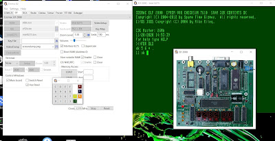
Just found Emma 02 , an 1802 Emulator that can emulates several RCA 1802 systems and could not resist trying a quick install, and it worked.

Internet home         https://www.emma02.hobby-site.com/
(Download             https://www.emma02.hobby-site.com/download.html )
Facebook               https://www.facebook.com/emma02.emu/
Github                    https://github.com/etxmato/emma_02

After the easy installation on my windows machine i did run it.
On the tab "Elf" i pushed at the [Start] button. (bottom left)In the green terminal screen 'For help type HELP.' at the >>> prompt type FOR NEW  or FOR OLD start a Forth.
(It is also possible to type FORTH , and the system wil ask OLD or NEW ) 

It is also possible to emulate other 1802 systems e.g. the COMX-35 (an RCA 1802 computer i never owned) that runs a Basic version.

Thursday, November 19, 2020

FORTH on Arduino -3- (Funduino Joystick game shield)

Having eForth running on my Arduino testing some I/O is what i wanted. Some years ago i posted https://blog.jeronimus.net/2017/04/funduino-joystick-shield.html about an Arduino joystick / button shield. This cheap shield has a joystick some input buttons. (And some connection headers that i did not use in this test.)  
There are several versions of this board. I have the Funduino V1.A The shield gives your Arduino the functionality found on the old Nintendo controllers. It can be used for gaming or control hardware.
2 analog inputs and some digital Ideal to start with this this shield with eForth to do some simple input tests. 


The table below lists how the buttons are connected to the Arduino 

ArduinoButtonPort&bit
D2Key A UPPD2
D3Key B RIGHTPD3
D4Key C DOWNPD4
D5Key D LEFTPD5
D6Key E StartPD6
D7Key F SelectPD7
D8Analog buttonPB0
A0AnalogX JoystickAnalog0
A1AnalogY JoystickAnalog1


The ForthArduino1.pdf contains several I/O examples that can be tested with this board: 

For the analog ports
Paragraph 3.5 mentions
If you connect an external analog signal source to the A0 pin, then type the following commands to read its analog value:

27 C!    \ setup A0 as input pin, which is on PC-0 port
 1 28 C! \ turn on pull-up resister on A0 pin
40 7C C! \ setup reference and multiplexer inputs
C3 7A C! \ start conversion
78 ?     \ display results 78 = low byte 79 = high byte

Example for digital port  ( D8 PB0 button of joystick)

 0 24 C! \ make all Port B pins input
 1 25 C! \ turn on pull-up resistor for Line 8
23 C@  . \ read PINB port and show its contents

23 C@ . \ repeat with switch on and off

What i especially like about eForth on Arduino is that using the terminal you can interactively test and play with the system to adapt it to your own needs.
The AVR Family databook / ATmega328P datasheet contains detailed info about all the internal registers. Also the multiple functions of the pins are explained.
Also you can find the info that i summarized in the table below.


Data register

Data direction
 register
Input pin address

PortBPORTBDDRBPINB
D8
Analog button
0x05 (0x25)
0x04 (0x24)
0x03 (0x23)
PortCPORTC
DDRC
PINC

0x08 (0x28)0x07 (0x27)0x06 (0x26)
PortDPORTD
DDRD
PIND
D2-D7
Key A - F
0x0B (0x2B)0x0A (0x2A)0x09 (0x29)


For reading the other buttons you need to read portD.
 0 2B C! \ make all Port B pins input
FF 2A C! \ turn on pull-up resistor for all lines
29 C@ .  \ read PINB port and show its contents

Some simple words to play with the shield and print the output :
: .PD  0 2A C! FF 2B C! 29 C@ . ;              / Print PortD  ( Buttons)
: .PB  0 24 C!  1 25 C! 23 C@ . ;              / Print PortB ( Joystick button)
: .PX 27 C!  1 28 C! 40 7C C! C3 7A C! 78 ? ;  / Print Joystick X value
: .PY 27 C!  1 28 C! 41 7C C! C3 7A C! 78 ? ;  / Print Joystick Y value
: .JOY .PB .PX .PY ;                           / Print all Joystick values

I used short cryptic words like .PB. More descriptive would be .PrintPortB, For playing with the system it would require more typing more characters. 

In Forth it is also possible to change the output to binary to easy see the bits corresponding to each button:
2 BASE !   /  Set Binary output 
HEX        /  Set Hexadecimal output

Hope this Arduino Forth ( eForth) introductory blog article can be help others starting to use Forth on Arduino.

Tuesday, November 17, 2020

FORTH on Arduino -2-

When i wrote FORTH on Arduino -1- i had some open questions. Now i have some answers and info how to proceed. I did not try it yet. However i like to post it as a short quick update about  eForth in my 'FORTH on Arduino' series.

- To trick the Arduino so it will start a special Forth word if no terminal input is received within a certain time or depending on a High or Low value on an Arduino pin to create a simple reconfigurable embedded Forth system. should be quite easy. In the book 'eForth and Zen' and especially the ForthArduino_1.pdf  ( Tao of Arduino ) by Dr. Chen-Hanson Ting is info how to create a turn key system that, after a reset or at power on starts with Forth word.
A quote from chapter  "3.6 Build a Turnkey Application" where a forth word APPL is created:

To turnkey this application so that it executes APPL command on booting-up, type the following commands:
' APPL 'BOOT ! \ store address of APPL in variable 'BOOT
$100 ERASE \ erase flash
$100 $100 WRITE \ save RAM $100-17F to flash $100-17F
$180 ERASE \ erase flash if this page is used
$180 $180 WRITE \ save RAM $180-1FF to flash $180-1FF

- Using I2C can be done in different way. i would like to use the Arduino library and interface this to Forth. This to also know how to use other Arduino libraries and code that already works in a 'plain Arduino environment'.  I am still looking for more info about this.
Another option is controlling the IO pins fir I2C direct from within Forth as e.g. explained in   https://arduino-forth.com/article/arduino_I2Cinterface


FORTH on Arduino -1-

 FORTH on Arduino

Before trying to install a Forth where changing the bootloader is needed i wanted to experiment with Forths that are more 'plug an play'.

First i tried Yaffaforth

After downloading unpacking it tried to compile it. Seemed that it also needed install FreeMemory. After installing this and spending more time than desired it still kept giveing error messages e.g. 'ip' was not declared in this scope .

As in the Yaffaforth information i found on internet a relative old Arduino version is used and the Yaffaforth is also relative old i decided to try stop and try another Forth for Arduino.

Therefore i moved to eforth of Dr. Ting . This Forth compiled without problems on my PC. Also uploading to the Arduino was easy.

The only issue that needed to be fixed was my terminal configuration. In the code i found the baud-rate and i needed to adjust some CR LF settings. It looks great however i did not yet had time to read all documentation to find a solution for the following issues:

- I want to use more IO including I2C within Forth on my Arduino.

- BUILD DOES> that later changed to CREATE DOES> is not available in eforth. I wanted to use this like i used it years on my RCA 1802 computer.

- How to trick the Arduino so it will start a special Forth word if no terminal input is received within a certain time or depending on a High or Low value on an Arduino pin. This to create a simple reconfigurable embedded Forth system.

So i still have a lot to learn and hope to post something about this process on this blog.. eforth seems a great Forth for Arduino. It was easy to install was for me worth the time spend and i want to investigate it further as you also seem to have access to all arduino libraries.

Monday, November 16, 2020

EPROM programmer -2-

This is part 2 of my post about my EPROM programmer. I did not yet tested the EPROM programmer however i want to report that i have tested the I2C_EEPROM that i mounted on my board.

As i mentioned in my last post , having an EEPROM on a UV EPROM board is perhaps a little confusing. It think it can be a valuable add on. Use cases for the additional EEPROM can be;

  • using the EPROM programmer as stand alone device to write the same program to several EPROMs
  • reading several EPROMS to the EEPROM for later investigation
  • comparing EPROMs with EEPROM
  • creating an EPROM emulator
  • using a spare PCB of this programmer to add an I2C_EEPROM to a project (most PCB manufacturers (like JLCPCB send out multiple PCBs)
  • .........

I have recently tested an I2C EEPROM on my PCB and it works fine.
The first sketch used for testing is the sketch below (as found at several places on the internet) and some variants i created of it:
/*
* I2C EEPROM sketch
* this version for 24LC128
*/
#include <Wire.h>
const byte EEPROM_ID = 0x50; // I2C address for 24LC128 EEPROM
// first visible ASCII character '!' is number 33:
int thisByte = 33;
void setup()
{
Serial.begin(9600);Wire.begin();
Serial.println("Writing 1024 bytes to EEPROM");
for (int i=0; i < 1024; i++)
{
I2CEEPROM_Write(i, thisByte);
// go on to the next character
thisByte++;
if (thisByte == 126) // you could also use if (thisByte == '~')
thisByte = 33; // start over
}
Serial.println("Reading 1024 bytes from EEPROM");
int thisByte = 33;
for (int i=0; i < 1024; i++)
{
char c = I2CEEPROM_Read(i);
if( c != thisByte)
{
Serial.println("read error");
break;
}
else
{
Serial.print(c);
}
thisByte++;
if(thisByte == 126)
{
Serial.println();
thisByte = 33; // start over on a new line
}
}
Serial.println();
}
void loop()
{
}
// This function is similar to EEPROM.write()
void I2CEEPROM_Write( unsigned int address, byte data )
{
Wire.beginTransmission(EEPROM_ID);
Wire.write((int)highByte(address) );
Wire.write((int)lowByte(address) );
Wire.write(data);
Wire.endTransmission();
delay(5); // wait for the I2C EEPROM to complete the write cycle
}
// This function is similar to EEPROM.read()
byte I2CEEPROM_Read(unsigned int address )
{
byte data;
Wire.beginTransmission(EEPROM_ID);
Wire.write((int)highByte(address) );
Wire.write((int)lowByte(address) );
Wire.endTransmission();
Wire.requestFrom(EEPROM_ID,(byte)1);
while(Wire.available() == 0) // wait for data
;
data = Wire.read();
return data;
}

However i did first run an I2C scan program to check the ID of the EEPROM. And with the EEPROM connected i found indeed the ID value 0x50 as used in the script.
Reading writing to te EEPROM works fine. Next step to make EPROM programmer working is testing and writing code for the SN 74595 shift registers.


Meanwhile i am also working on a redesign of my EEPROM shield for multiple EEPROMs. I did not yet order my first design at e JLCPCB  as i had some ideas for improvements and features that i wanted to add. 
On my 'Arduino to do list' is also writing a a better memory dump program for these EEPROMs and also running Forth code on the Arduino Uno.