

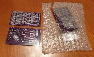
There are several shield available for the Arduino Uno that can help with learning, experimenting and testing. I created a simple "D2-D9 Led tester shield" that can be used to test some simple Arduino output.

It is a simple PCB with 8 Leds and resistors 3 standard push buttons and a reset button.
I called my shield the D2-D9 Led tester shield. On the PCB there are no hard paths from D2-D9 to the Leds or the buttons (Except the Reset button). With some jumpers the Leds can be easy connected, disconnected or reconfigured.
Each led has a 5 pin male DuPont connector and two jumpers connected according to the diagram below.

On the first PCB i soldered i used two different color jumpers to easy show the connection. However it is also possible to do things different, e.g. using wire bridges to hard wire the Leds.
The middle pin Dn is D2 to D9. In the table below i used a (anode) and k (kathode) for the led connections. However in reality it is an Led with resistor.

| GND | k | Dn | a | VCC | (no jumpers / nothing connected) led off (See photo U2) |
| GND | k | Dn | a | VCC | "power mode" Led always on (See photo U3) |
| GND | k | Dn | a | VCC | Led between GND and Dn Dn High will turn led on (See photo U4) |
| GND | k | Dn | a | VCC | Led between Dn and VCC Dn Low will turn led on (See photo U5) |
To connect another data-pin from the Arduino than the corresponding Dn in the 5 in connector a Dupont wire can be used.
Besides the easy stacking it has the advantage that, as with the cheap PCB services you get minimal 5 PCBs, unused PCBs can be easy made useful.
( Update 18NOV2022: Added this project to my Github https://github.com/JanJeronimus/Arduino_LedShield )


No comments:
Post a Comment