


The kit contains more transistors than needed so after building an testing i now have some extra transistors. An instruction manual or schematic was not included. Information which components to place where was on the PCB


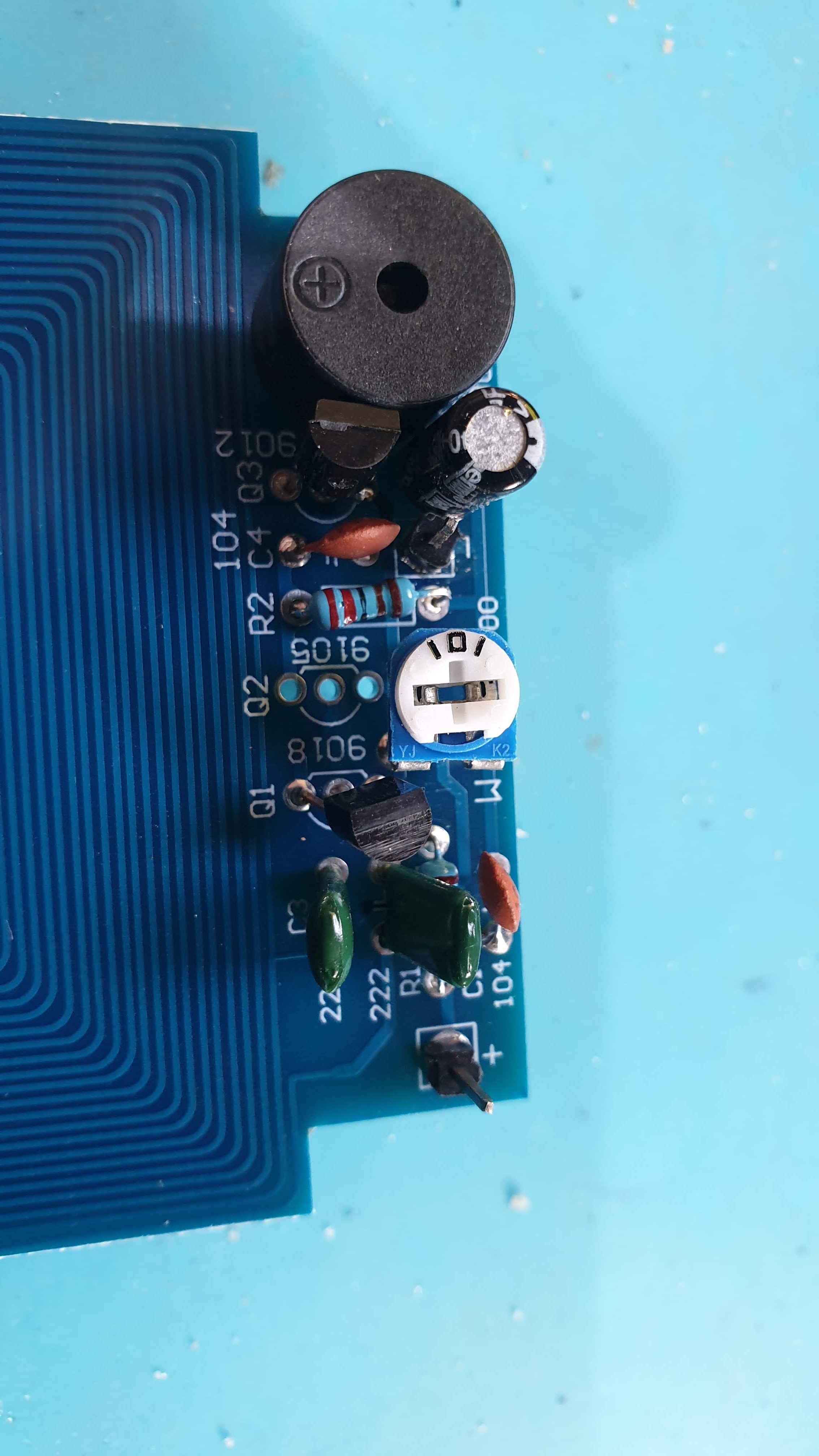
I included a photo of the front and back of the PCB.
After assembling i powered the metal detector using 3 1.5 AA batteries (= 4.5V). This metal detector seems to work better than the one in my Metal detector -1- blog post. This second metal detector only has a buzzer. not an led. See picture below. It only gives a signal when metal is near the PCB. (It is possible to create a (false) signal by moving the batteries and battery wires near the detection coil. The pot meter can be used to adjust the sensitivity.
I have found a circuit for a metal detector using a 555 timer and i have some of these 555 times i stock.
Perhaps, some time, i also build a metal detector using the 555. However i am also working on other projects and received some PCBs and other components for these project. And for now i have a nice working metal detector so i want to give priority for these other projects.
Perhaps, some time, i also build a metal detector using the 555. However i am also working on other projects and received some PCBs and other components for these project. And for now i have a nice working metal detector so i want to give priority for these other projects.


No comments:
Post a Comment